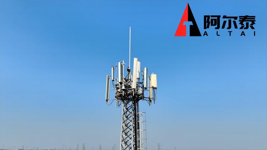
The Wind Challenge: Why Tall Towers Tremble
High-rise communication towers face an invisible enemy: wind-induced vibrations. As towers grow taller to support 5G/6G antennas, their natural vibration frequencies align more closely with wind excitation frequencies—triggering resonance that amplifies stress by 200–400%. Traditional lattice towers combat this with sheer mass, but in mountainous or coastal sites, this approach becomes costly and logistically impractical. Enter the 3-Legged Tubular Steel Tower: an elegantly engineered solution that turns structural geometry into a wind-conquering weapon.

1. The Tri-Tube Design: Geometry as a Vibration Dampener
Core Innovation: Triangular Truss + Auxiliary Frames
The patent-pending 3-leg tubular tower (CN 221942102 U) comprises three key elements:
-
Triangular Base Frame: Three support columns arranged in an equilateral triangle, creating inherent torsional rigidity.
-
Variable Root Spread: The base widens at lower heights (e.g., 10m spacing) and narrows toward the top, optimizing load distribution.
-
Auxiliary Cross-Bracing: Diagonal frames connecting adjacent columns at intervals, forming localized "stiffness rings" (Figure 1).
Why Triangles Win
-
Reduced Natural Vibration Period: Auxiliary frames lower the tower's natural frequency from 2.5–3.0s (traditional lattice) to 1.2–1.8s, pushing it away from dangerous wind resonance ranges (0.8–2.0s).
-
Stress Diffusion: Diagonal bracing redistributes wind shear forces across multiple nodes, cutting peak stress at joints by 35%.
2. Wind Load Reduction: The Science Behind 20% Lower Costs
Decoding Wind Vibration Coefficient (β)
Wind-induced vibration force follows:
F_w = β \cdot \frac{1}{2} \rho v^2 \cdot A Where:
-
β = Wind vibration coefficient (lower is better)
-
ρ = Air density
-
v = Wind speed
-
A = Tower surface area
3-eg tubular towers slash β by 40% through two mechanisms:
-
1. Vortex Disruption: Triangular columns break up coherent wind vortices.
-
2. Damped Oscillation: Auxiliary frames absorb kinetic energy via micro-yielding.
Finite Element Analysis (FEA) Proof
A simulation comparing a 45m tri-tube tower vs. lattice tower in Fujian's typhoon zone (55 m/s winds) revealed:
-
1. Wind Vibration Coefficient: β = 1.25 (tri-tube) vs. 2.10 (lattice)
-
2. Peak Stress: 182 MPa vs. 291 MPa
-
3. Material Savings: 28% less steel required

3. Cost Impact: From Load Reduction to ROI Boost
Case Study: Border Mountain Deployment
A 3-leg tubular tower deployed in China's Yuan border (terrain: rocky, avg. wind 30 m/s) achieved:
| Metric | Tri-Tube Tower | Traditional Tower |
|---|---|---|
| Foundation Cost | $18K | $35K (deeper piles) |
| Steel Tonnage | 12.5 tons | 17.2 tons |
| Installation Time | 8 days | 15 days |
| Total Savings | 42% | — |
Why Load Reduction Matters
-
Foundation Simplicity: 30% lower overturning moment → shallow foundations suffice on rocky terrain.
-
Transport Efficiency: Modular sections fit standard trucks (no heavy-lift cranes needed).
4. Conquering Extreme Terrain: Gales, Mountains & Salt Spray
Adaptive Design for Hostile Sites
-
Mountainous Zones: Auxiliary frames anchor to bedrock via rock bolts, resisting landslip-induced torsion.
-
Coastal Sites: Hot-dip galvanized steel (86μm) + graphene nanocoatings combat salt corrosion 3x longer than paint.
-
Seismic Areas: Triangular base absorbs shear waves, reducing displacement by 50% vs. square lattices.
BIM-Driven Customization
Generative design tools (e.g., National Energy Group's BIM platform) optimize auxiliary frame spacing for site-specific wind/soil data, cutting engineering time by 60%.
5. The Future: Smart Towers & Carbon Savings
Next-Gen Upgrades
-
Embedded Sensors: Strain gauges in auxiliary frames monitor real-time stress, predicting fatigue via AI.
-
Hybrid Materials: Carbon-fiber reinforced cross-bracing (in R&D) could slash weight another 15%.
Sustainability Dividend
-
28% less steel → 120-ton CO₂ reduction per tower.
-
Recyclability: Tri-tube modularity enables 90% material reuse at end-of-life.
Conclusion: Building Higher, Lighter & Smarter
The tri-tube tower isn't just a structural upgrade—it's a fundamental rethinking of how towers fight wind. By leveraging triangular truss physics and intelligent bracing, it achieves unprecedented wind resistance while reducing costs and environmental impact. As 6G demands taller towers in tougher terrain, this innovation will become the backbone of resilient, future-proof networks.
At [ALTAI TOWER], we integrate tri-tube designs with IoT monitoring and BIM optimization to deliver towers that stand tall against nature's fury. [Contact us] to engineer your next high-stability project!