Steel utility poles are rapidly becoming the cornerstone of modern, resilient low-voltage (LV) power distribution networks. Their dominance stems not just from their advantages over concrete, but from sophisticated engineering in their structure, fabrication, and crucially, corrosion protection. Let's delve into the technical heart of these essential grid components.

1. Structural Design: Form Follows Function & Force
LV utility poles are designed to withstand complex loads: vertical weight (conductors, equipment), horizontal wind pressure, and potential ice accumulation. Key structural approaches include:
-
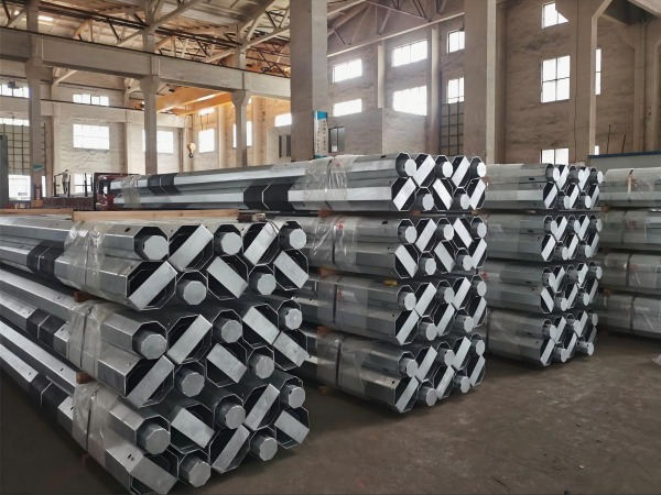
Tapered Monopoles (Conical): The most common design. The pole diameter and wall thickness gradually decrease from the robust base (high bending moment) to the lighter top. This design:
-
-Optimizes Material: Uses steel only where strength is needed.
-
-Improves Aesthetics: Creates a sleek profile.
-
-Enhances Performance: The conical shape efficiently channels loads to the foundation.
-
-
Multi-Section Poles (Combined): Used for very tall poles or specific loading requirements. Sections (usually 2 or 3) are joined together using:
-
-Flange Connections: Heavy-duty steel plates welded to the ends of each section, bolted together. Requires precise machining and bolting procedures. Offers high strength and rigidity. Common for larger poles.
-
-Socket (Slip Joint) Connections: The upper section has a reduced diameter end that fits into the lower section. Fixed with through-bolts or shear pins. Faster installation but generally used for lighter loads or shorter heights than flange connections.
-
-
Design Principle: The cross-section (diameter, wall thickness) is meticulously calculated based on:
-
-Section Modulus: Determines the pole's resistance to bending moments caused by wind and conductor loads.
-
-Moment of Inertia: Influences resistance to buckling.
-
-Local Buckling Criteria: Ensures the thin steel walls don't buckle under compression.
-
-Deflection Limits: Ensures the pole doesn't bend excessively under load, maintaining safe conductor clearances.
-
2. Manufacturing Process: Precision from Plate to Pole
Quality manufacturing is paramount for performance and longevity. The core process involves:
-
Material Selection & Cutting: High-quality structural steel plates (e.g., ASTM A572 Grade 50) are precisely cut to trapezoidal shapes using CNC plasma or laser cutters.
-
Rolling: The flat plates are fed through a series of rollers in a pyramid rolling machine. Progressive bending transforms the trapezoid into the conical or cylindrical shape. Precision control ensures consistent taper and roundness.
-
Longitudinal Welding: The rolled plate's edges are brought together and welded along the entire length using Submerged Arc Welding (SAW). SAW is favored for:
-
-Deep Penetration: Creates a strong, uniform weld through the entire thickness.
-
-High Deposition Rates: Efficient for long seams.
-
-Excellent Quality & Consistency: Produces smooth, slag-free welds with minimal spatter under a protective flux layer.
-
-Critical QC: Weld integrity is non-negotiable. Strict procedures govern pre-heating (if required), weld parameters (voltage, current, speed), and post-weld inspection. Non-Destructive Testing (NDT) like Ultrasonic Testing (UT) or Radiographic Testing (RT) detects internal flaws (porosity, lack of fusion, cracks).
-
-
Straightening & Sizing: The welded shell may pass through sizing rolls or be straightened using hydraulic presses to ensure perfect alignment and dimensional accuracy.
-
End Preparation: Base plates are welded on for direct burial or anchor bolt connection. Top plates or connection hardware (flanges or socket ends) are welded on. Holes for equipment mounting are precisely drilled or punched.
-
Cleaning & Surface Preparation (Critical for Coating): The pole undergoes rigorous cleaning:
-
-Degreasing: Removes oils and greases.
-
-Pickling: Acid bath removes mill scale and rust.
-
-Fluxing: Applies a protective layer (often zinc ammonium chloride) to prevent oxidation before galvanizing and promote zinc adhesion.
-

3. Corrosion Protection: The Lifeline Defense
Protecting steel from the elements is the single most critical factor ensuring decades of service. Two primary systems dominate LV poles:
-
1. Hot-Dip Galvanizing (HDG): The Gold Standard
-
Process: The meticulously cleaned pole is immersed in a bath of molten zinc (typically ~450°C / 840°F). A metallurgical reaction occurs, forming a series of zinc-iron alloy layers topped by a layer of pure zinc.
-
Key Standards: ASTM A123/A123M is the primary specification in North America for galvanizing structural steel. It dictates:
-
-Coating Thickness: Minimum requirements based on steel thickness (e.g., for steel >6mm, min avg. thickness is 85µm / 3.4 mils). Thicker steel generally requires/thicker coating.
-
-Adherence: The coating must withstand specific tests without flaking.
-
-Appearance: Specifies acceptable surface conditions.
-
-
Advantages: Exceptionally durable, long-lasting (50+ years typical), provides cathodic (sacrificial) protection to exposed steel edges or scratches, low maintenance.
-
Quality Control: Coating thickness is measured magnetically (e.g., Elcometer) at multiple points. Visual inspection checks for uniformity, lumps, bare spots, and ash inclusions. Adherence is tested by quenching or light hammering.
-
-
2. Advanced Coatings (Polymer/Powder Coating):
-
Process: Applied after galvanizing (Duplex System) or directly onto specially prepared steel (less common for ground-line exposure). Typically involves spraying electrostatically charged powder (epoxy, polyester, polyurethane) onto the pole, which is then cured in an oven, forming a thick, continuous film.
-
Advantages: Wide range of colors (aesthetics), excellent UV resistance, good chemical resistance, smooth finish. In a duplex system, it adds significant extra lifespan by shielding the zinc layer.
-
Applications: Increasingly popular, especially for urban areas where aesthetics matter, or combined with HDG for maximum protection. Direct-to-steel coatings require meticulous surface preparation (e.g., abrasive blast cleaning to Sa 2.5 profile) and are generally used for above-ground sections or less corrosive environments than HDG alone.
-
Standards: ASTM standards like D4138 (adhesion), D3359 (cross-hatch adhesion), D714 (blistering), D4060 (abrasion), D4585 (salt spray) are relevant for testing coating quality.
-

Conclusion: Engineering Excellence for Grid Resilience
The widespread adoption of steel tubular poles in LV networks is built upon a foundation of sophisticated structural engineering, precision manufacturing – particularly high-integrity welding – and, most critically, advanced, rigorously controlled corrosion protection systems. Understanding the interplay between the tapered or multi-section design, the robust manufacturing process with its emphasis on weld quality, and the science behind coatings like hot-dip galvanizing (governed by standards like ASTM A123) reveals why these poles offer superior longevity, reliability, and lifecycle value. As grids face increasing demands from urbanization and extreme weather, the technical excellence embedded in the design, fabrication, and corrosion defense of steel tubular poles ensures they will remain a vital part of our power infrastructure for decades to come.
Learn more at www.alttower.com