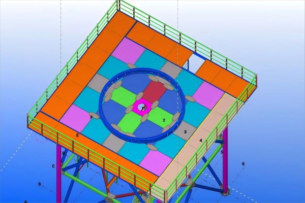
Radar towers serve a uniquely demanding purpose. Unlike communication towers that simply hoist passive antennas, radar towers must provide an exceptionally stable platform for rotating, precision‑sensing equipment. A slight structural deflection, an unexpected vibration mode, or—just as critically—an access component that introduces unwanted flexibility can compromise the radar's pointing accuracy and data fidelity.
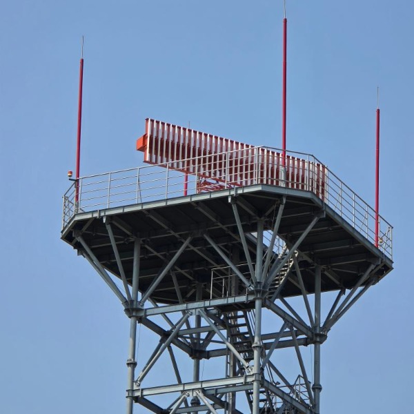

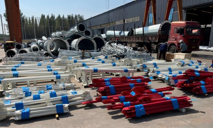
radar support tower


Yet these towers must also be accessible. Technicians need to climb them for routine calibration, antenna maintenance, and emergency repairs. The challenge is to integrate safe climbing systems and equipment platforms into the tower's structural envelope without sacrificing the stiffness that radar precision demands.


The Tension Between Access and Stiffness

Radar support structures are governed by stringent dynamic requirements. A tower's natural frequency must be kept sufficiently high, and well separated from the forcing frequencies generated by the rotating antenna and environmental wind loads, to avoid resonant coupling that would smear radar images. Every added component—a ladder rung, a platform support bracket, a cable guide—alters the structure's mass and stiffness distribution. Poorly designed access features can introduce local flexibility, create stress concentrations, or add mass in locations that lower critical natural frequencies. The objective, therefore, is to embed safety and access features into the tower's primary structural logic rather than treating them as afterthoughts.


Regulatory Framework for Safe Access

Radar towers, like communication towers, must comply with an evolving suite of safety standards. In North America, the ANSI/ASSE A10.48‑2016 Standard establishes comprehensive criteria for safe work practices on communication structures, covering everything from fall protection to climbing facilities. This standard has become the benchmark for the industry. Meanwhile, OSHA regulations require 100% fall protection for employees exposed to elevations above 6 feet while working on towers. For fixed ladders over 24 feet, OSHA historically permitted ladder cages, but the regulatory trend has shifted decisively: cages are being phased out, with a 2036 deadline for replacement. Modern systems rely on vertical lifelines or rigid rail fall‑arrest systems, which are more effective at actually stopping a fall.


Internationally, EN 353‑1:2014+A1:2017 governs guided type fall arresters on rigid anchor lines, while ANSI Z359.16‑2016 covers safety systems for climbing fixed ladders. Products compliant with these standards, such as the stopcable system, feature detachable fall arresters with built‑in energy absorbers that lock instantly upon a fall and minimise free‑fall distance.
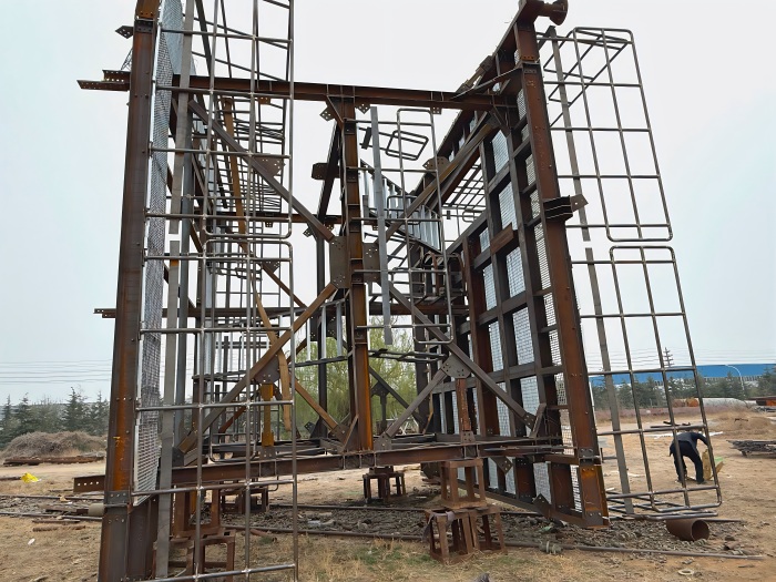

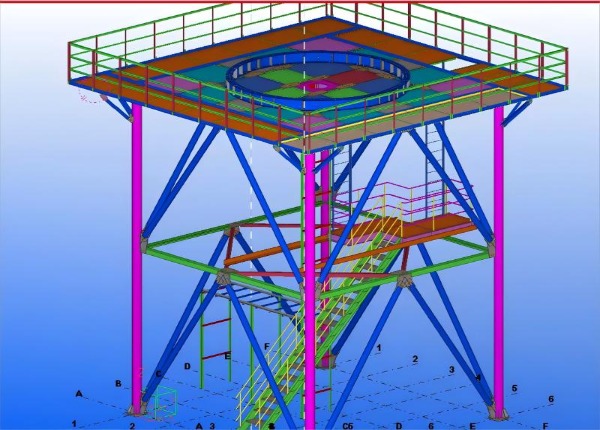
radar lattice tower


Choosing the Right Climbing System: A Comparative Overview

For radar towers, not all climbing safety solutions are equal. The table below compares the main options:


System Fall Protection Mechanism Key Features Suitability for Radar Towers
Fixed Ladder (No Protection) None—user relies on 3‑point contact Lowest cost, simplest installation Not acceptable—fails regulatory compliance and presents extreme risk
Ladder with Cage Physical barrier prevents falling sideways/backward Simpler for untrained users; cages do not arrest vertical falls Phased out—offers false security and complicates rescue; not recommended for new builds
Vertical Cable/Rail Safety System Harness‑mounted fall arrester slides along permanently installed cable Arrests falls within inches; allows free climbing with both hands; can be retrofitted Recommended—meets ANSI/OSHA requirements; minimal impact on tower stiffness; supports up to 4 users on one system
Personal Fall Arrest System (PFAS) Harness + lanyard attached to independent anchor point Highly effective but relies on correct user action and anchor availability Supplemental—suitable for platform work, but not as primary climbing system due to repeated connect/disconnect requirements

Key selection insights:

  1. Vertical cable systems (e.g., Latchways® TowerLatch or Tractel stopcable®) are increasingly the industry standard because they provide continuous attachment and do not require the user to disconnect at intermediate guides. The patented starwheel component enables smooth movement through cable guides without pulling cable out of the guides, a critical feature when climbing past multiple platform levels.

  2. For monopole radar towers, dedicated universal mounts are available (e.g., Universal Monopole Mount Safe Climb Systems), using 3/8″ galvanised wire rope with cable stand‑offs every 25 feet and a sealed anchor head with impact attenuator.

  3. Ladder cages should be avoided on new radar towers: they do not prevent vertical falls and can make rescue more difficult.
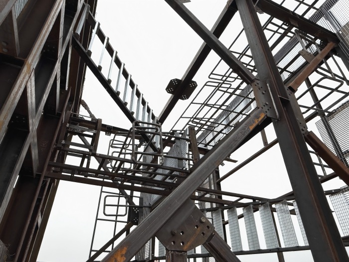

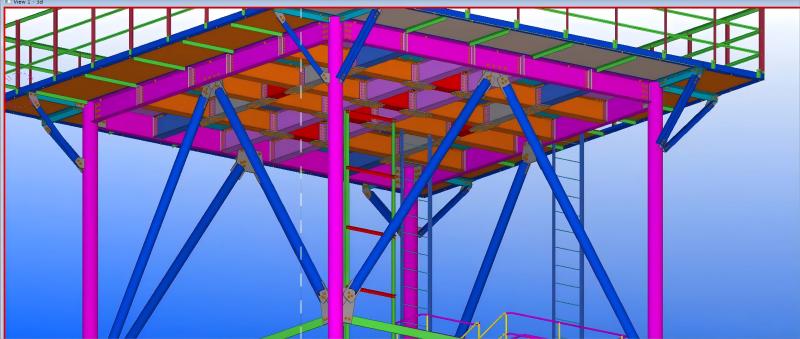
radar lattice support tower


Equipment Platforms: Access Without Compromising Stiffness

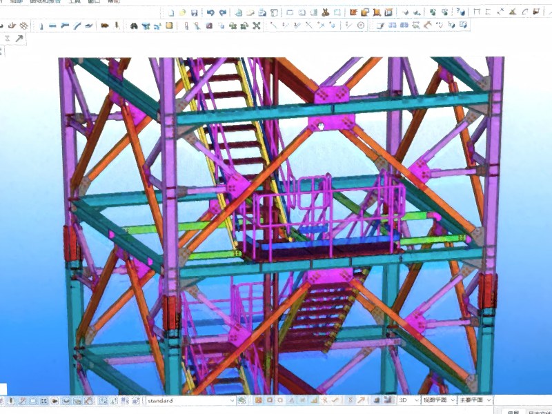
Radar towers typically feature multiple platforms: a lower platform for equipment access (e.g., at 26 m) and an upper platform at the radome level (e.g., at 30 m) where the radar antenna is installed. These platforms serve as maintenance work areas and provide mounting points for ancillary equipment. From a structural perspective, they must be integrated as stiffened diaphragms—their floor beams and bracing must contribute positively to the tower's overall rigidity.

Key design principles for platforms:

  1. · Full‑perimeter bracing: Platforms should be tied into all tower faces with cross‑bracing or stiffened decking to act as horizontal stiffening rings, preventing local mode shapes.

  2. · Load transfer: The platform's vertical load (technician weight, equipment, ice) must be transferred into the tower legs via dedicated connection nodes, not through the diagonal bracing alone.

  3. · Open vs. solid decking: Open steel grating is preferred over solid plate because it reduces wind load accumulation, improves visual inspection of members below, and sheds ice more readily.

Platforms also serve as rescue staging areas—required resting points on tall ladders, typically every 9 to 12 metres—where a worker can rest, change out fall protection gear, or await assistance.

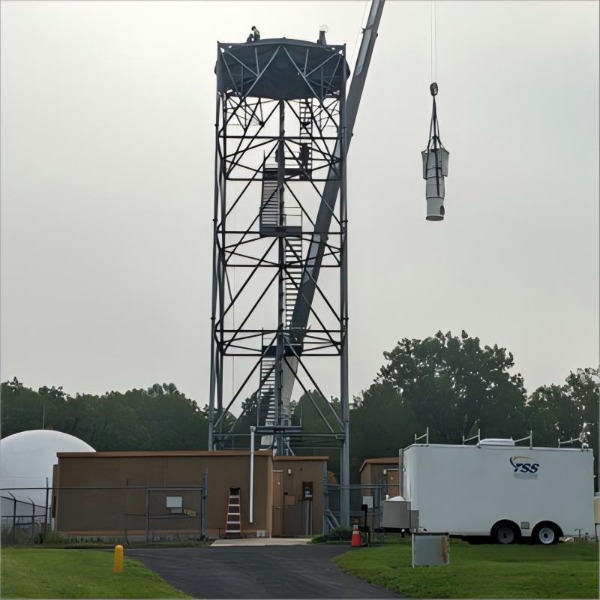
radar support tower


Lightning Protection Integration

Radar towers are often sited in exposed locations (mountains, coastlines) that make them vulnerable to lightning strikes. The tower's climbing systems and platforms must be integrated with the external lightning protection scheme:

  1. · Air terminations: Lightning rods or masts at the tower apex protect the radar antenna. Studies show that a single air termination raised to 38 m can protect the entire tower and antenna. With four terminations placed on the tower, each offers a protection radius of 45 m.

  2. · Down‑conductors: The steel tower itself serves as the primary down‑conductor, but all metallic access components (ladders, platform railings, cable guides) must be bonded to the grounding system to prevent side‑flashes.

  3. · Grounding: A ring earth electrode at the tower base, connected to all leg foundations, ensures safe dissipation of strike current without endangering personnel climbing the structure.

radar support tower


Structural Design for Serviceability

The ultimate goal of integrating safe climbing systems is to ensure that the tower can be serviced and maintained throughout its operational life without compromising radar performance. This means designing for:

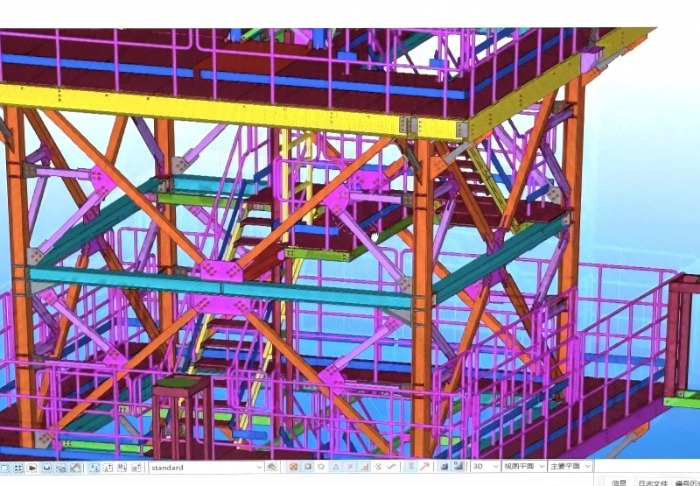
  1. · Fatigue resistance: The addition of platforms and ladders creates local stress raisers. Bolted connections are preferred over welded attachments at critical dynamic load paths to avoid introducing fatigue‑prone notches.

  2. · Dynamic compatibility: The mass of access systems must be accounted for in modal analysis. Distributed mass (ladders, cable guides) has a different effect on natural frequencies than concentrated mass (platform equipment).

  3. · Inspectability: Platforms should be positioned to allow visual access to bolted connections and welds in the tower legs, facilitating routine condition assessments.

radar support lattice tower


Conclusion

Access systems in radar towers are not peripheral add‑ons—they are integral to the structure's ability to be maintained, calibrated, and ultimately to perform its precision mission. The modern design approach mandates vertical cable fall‑arrest systems over outdated cages, stiffened platform diaphragms that enhance rather than degrade tower rigidity, and bonded lightning protection that safeguards climbing personnel. When properly integrated, safe climbing systems and equipment platforms enable the tower to be both accessible and accurate, fulfilling its dual role as a stable radar platform and a safe workplace for the technicians who keep it operational.


Ready to integrate safe, radar‑grade access systems into your next tower project? Contact our engineering team today for custom design support and a detailed quote.
Contact Us

Introduction

Critical infrastructure demands unparalleled reliability, and nowhere is this more crucial than for radar towers safeguarding aviation, maritime, and national security. These towers are strategically positioned in the most corrosive environments imaginable—exposed coastal zones where salt-laden air, high humidity, and intense UV radiation relentlessly attack structural steel. Ensuring their decades-long service life requires a deliberate, engineered approach to corrosion protection. This blog delves into the advanced defense strategies, centered on Hot-Dip Galvanizing (HDG) and specialized coating systems, that protect these vital assets.


radar mounts


1. The Unforgiving Enemy: Corrosion in Coastal Zones

The corrosion rate for steel in a marine environment can be 3 to 5 times faster than in a rural setting. The primary aggressors are:

  1. · Salt Aerosols: Airborne chloride particles deposit on surfaces, forming a highly conductive electrolyte that accelerates electrochemical corrosion.

  2. · High Humidity: Constant moisture facilitates the corrosion reaction, preventing protective films from forming.

  3. · Cyclic Conditions: Daily temperature and humidity fluctuations cause "breathing," which can drive salt and moisture into micro-cracks.

  4. · UV Degradation: Sunlight breaks down many organic polymer coatings, causing chalking, fading, and loss of film integrity.

For a radar tower, structural failure is not an option. The corrosion protection system must be designed from the outset for ultra-long-term performance with minimal maintenance.


2. The First Line of Defense: Robust Hot-Dip Galvanizing (HDG)

Hot-dip galvanizing forms the foundational, metallurgically-bonded barrier for the entire steel structure. For coastal zones, standard HDG is not enough; an enhanced process is required.

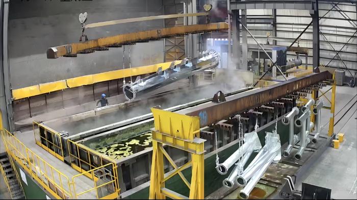
  • · The Process: The fabricated steel is immersed in a bath of molten zinc at around 450°C (840°F). This creates a coating comprised of a series of zinc-iron alloy layers, topped by a layer of pure zinc.

  • · Enhanced Specifications for Coastal Use:

    1. Increased Coating Thickness: We specify coatings that exceed standard requirements. For steel over 5mm thick, a minimum average thickness of 100-120 µm is targeted, in accordance with the most severe service categories of ISO 1461 (e.g., Category 4/5).

    2. Superior Surface Preparation: To ensure perfect adhesion, steel undergoes rigorous cleaning (degreasing, pickling) and fluxing. The quality of this preparation directly dictates the quality and longevity of the zinc coating.

    3. Controlled Withdrawal: The speed and angle at which the steel is withdrawn from the zinc bath are controlled to ensure a uniform, consistent coating, even on complex fabrications.

The HDG layer provides triple protection: a tough physical barrier, cathodic protection (where the zinc sacrificially corrodes to protect the underlying steel), and the unique ability to "heal" minor scratches through galvanic action.


galvanized radar support


3. The Secondary Shield: High-Performance Coating Systems

While HDG is exceptionally durable, adding a specialized coating system creates a synergistic "duplex system" that dramatically extends the service life of both the galvanizing and the coating.

  • · The Synergy of a Duplex System: The HDG layer prevents under-coating corrosion, which is the primary failure mode for paints. Simultaneously, the topcoat shields the zinc from direct exposure to the environment, significantly slowing its consumption rate. The combined system can offer 1.5 to 2.5 times the service life of either system alone.

  • · Coating Selection for Marine Atmospheres:

    1. Epoxy Primers: These are chemically resistant and provide excellent adhesion to the galvanized surface, which must be lightly sweep-blasted or treated with a T-Wash (etching primer) to ensure proper bonding.

    2. Polyurethane Topcoats: Chosen for their outstanding UV resistance, color and gloss retention, and superior weatherability. Aliphatic polyurethanes are the industry standard for a durable, flexible, and chemically resistant finish.

    3. Advanced Resin Systems (e.g., Polysiloxanes): For the most demanding applications, polysiloxane hybrids offer even better UV and corrosion resistance than polyurethanes, with higher dry film thickness (DFT) application in a single coat and superior durability.


weather radar support


4. A Cohesive, Long-Life Protection Strategy

The effectiveness of this defense lies in the integration of all components:

  1. · Design for Durability: The tower's design itself must avoid moisture traps, ensure good drainage, and provide adequate access for future inspection and maintenance.

  2. · Rigorous Quality Control: Every step—from surface preparation and HDG bath chemistry to coating DFT verification (measured with magnetic gauges) and adhesion testing—is meticulously controlled and documented.

  3. · Lifecycle Cost Advantage: While the initial investment in an HDG-plus-coating duplex system is higher, the dramatic reduction in maintenance, repainting, and risk of failure makes it the most cost-effective solution over the asset's entire lifecycle.


Conclusion

Protecting critical radar infrastructure in coastal zones is a battle fought with advanced materials science and precise engineering. By deploying a synergistic defense of thick, high-quality hot-dip galvanizing as a robust base, enhanced by a high-performance coating system tailored to withstand salt, sun, and moisture, we can ensure these vital towers stand guard reliably for decades. This multi-faceted approach to corrosion defense is not an expense; it is an essential investment in the resilience and security of our national critical infrastructure.


 Learn more at  www.alttower.com


Contact Us

Introduction

In the world of critical radar infrastructure, precision is everything. Modern radar systems, whether for meteorological monitoring, air traffic control, or defense, demand an exceptionally stable platform. Even minute structural vibrations or sway in a radar tower can introduce phase errors, distort beam patterns, and degrade data quality, leading to a phenomenon known as "structural interference." Achieving zero interference is, therefore, not an aspirational goal but a fundamental engineering requirement. This blog delves into the sophisticated design principles and technologies employed to ensure that the tower itself remains an invisible, stable host for the sensitive equipment it carries.


radar tower for sale


1. The Enemy of Precision: Sources of Vibration and Sway

A radar tower is a dynamic structure constantly subjected to forces that induce motion. The primary culprits are:

  1. Wind Loading: The most significant and persistent force. It creates both static push (mean deflection) and dynamic excitation from vortex shedding and buffeting, leading to resonant vibrations.

  2. Vortex Shedding: As wind flows past the tower, it creates alternating vortices that detach from either side, generating a periodic lateral force. If this frequency aligns with the structure's natural frequency, it can cause significant, sustained vibration.

  3. Equipment-Induced Vibration: The rotation of the antenna and the operation of internal machinery can transmit low-amplitude, high-frequency vibrations through the structure.

  4. Seismic and Environmental Loads: In certain regions, seismic activity and thermal expansion/contraction can also contribute to structural movement.

The consequence of these movements is a deviation in the radar's pointing angle, which can manifest as blurred imagery, inaccurate target tracking, and reduced resolution.


radar tower for sale


2. Foundation of Stability: Dynamic Characteristic Analysis

The first and most critical step in designing for stability is a comprehensive Dynamic Characteristic Analysis. This involves creating a detailed finite element model (FEM) of the entire structure to predict its behavior under dynamic loads.

  1. Natural Frequency and Mode Shapes: Engineers calculate the tower's fundamental natural frequencies and their corresponding mode shapes (the pattern of deformation during vibration). The primary design objective is to tune these frequencies away from the dominant forcing frequencies of the wind (vortex shedding) and the rotating radar antenna.

  2. Wind Tunnel Testing: For critical applications, scale models of the tower are tested in wind tunnels. This validates the computational models and provides precise data on wind forces, including the critical wind speeds that trigger vortex-induced vibrations (VIV).

  3. Aeroelastic Analysis: This advanced simulation assesses the interaction between inertial, elastic, and aerodynamic forces to predict complex phenomena like galloping and flutter, ensuring stability across the entire operational wind speed range.


3. Taming the Motion: The Application of Dampers

Knowing the dynamic characteristics allows engineers to implement targeted solutions to dissipate vibrational energy. Dampers are the key active components in this defense.

  1. Tuned Mass Dampers (TMDs): A TMD is a passive device consisting of a mass, springs, and a damper that is precisely "tuned" to a specific problematic frequency of the tower. When the tower begins to vibrate at that frequency, the TMD oscillates out of phase, counteracting the motion and dissipating the energy as heat. For tall radar towers, TMDs are highly effective at mitigating both wind-induced sway and vibration.

  2. Viscous Fluid Dampers: These act as hydraulic shock absorbers installed within the tower's bracing. They are velocity-dependent, meaning the faster the structure moves, the greater the resisting force they generate. They are excellent for absorbing energy from sudden gusts and seismic events.

  3. Helical Strakes: For mitigating vortex-induced vibration, helical strakes are a simple yet effective aerodynamic solution. These spiral-shaped fins attached to the upper sections of the tower disrupt the coherent formation of vortices, preventing the buildup of resonant forces.


weather radar tower for sale


4. Form Follows Function: Structural Form Optimization

The very shape of the tower is the first line of defense against dynamic excitation. Optimizing the structural form reduces the excitation forces at their source.

  1. Aerodynamic Cross-Sections: Moving away from circular cylindrical sections to polygonal (e.g., octagonal) or tapered profiles can significantly alter the wind flow and raise the critical wind speed for vortex shedding.

  2. Tapered Design: A tower that tapers with height not only optimizes material use but also changes the structural dynamics, often resulting in higher natural frequencies and reduced wind loads on the upper sections.

  3. Stiffness and Bracing Optimization: The structural system is designed for maximum torsional and lateral stiffness. Advanced bracing patterns (like K-bracing or X-bracing) are analyzed and optimized to ensure a stiff, robust platform that minimizes deflection under operational loads.


5. Material Selection and Fabrication Integrity

The choice of materials and the quality of fabrication are crucial to realizing the theoretical design.

  1. High-Strength Steel: Using high-strength, low-alloy steels (e.g., Q345, Q420) allows for slimmer, lighter members that maintain high stiffness, contributing to a favorable strength-to-weight ratio and dynamic performance.

  2. Bolted vs. Welded Connections: While welding offers seamless connections, high-strength bolting in critical, field-assembled joints allows for precise pre-tensioning, which can enhance damping and structural integrity by minimizing slip in semi-rigid connections.

  3. Hot-Dip Galvanizing (HDG): Beyond corrosion protection, a uniform, high-quality HDG coating ensures the long-term preservation of the surface characteristics and cross-sectional geometry, which are essential for maintaining predicted aerodynamic performance.


radar tower for sale


Conclusion: A Symphony of Engineering for Invisible Performance

Achieving zero interference in a radar tower is a multi-disciplinary endeavor that blends civil, mechanical, and aerodynamic engineering. It begins with a deep understanding of the dynamic forces at play, continues through sophisticated modeling and optimization of the structure's form, and is finalized with the strategic implementation of damping technologies. By rigorously controlling structural vibration and sway, engineers create a platform that is not merely a support structure, but a seamless extension of the radar itself—enabling it to perform with the pinpoint accuracy that modern critical systems demand. In this high-stakes field, a stable tower is the silent guardian of data integrity.


 Learn more at   www.alttower.com


Contact Us

keyboard_arrow_up