With the continuous advancement of science and technology and the development of industrialization, chemical production has become an indispensable and important industry in modern society. During chemical production, maintaining a clean and safe production environment is particularly important. However, the presence of metallic iron often has a negative impact on the production process. To address this issue, fully automatic iron removers have emerged as a key piece of equipment in chemical production.


Fully automatic iron removerFully automatic iron remover


First, let's discuss the working principle of a fully automatic iron remover.

A fully automatic iron remover uses a high-strength magnetic source (such as a permanent magnet or electromagnetic coil) to generate a magnetic field, automatically attracting ferromagnetic impurities from the material. Its core advantages are:

Continuous operation: No downtime for cleaning is required, as automatic scraping and iron removal mechanisms ensure uninterrupted operation.

Intelligent identification: Combining metal sensors and a PLC control system, it accurately detects and separates ferrous impurities.

High adaptability: Suitable for a variety of material forms, including powders, granules, and liquids, and featuring corrosion- and high-temperature resistance, it meets the demands of specialized chemical environments.


Why fully automatic iron removers play such important roles in chemical production? The fundamental reason is this: Iron impurities in chemical raw materials can cause multiple problems:

Catalytic side reactions: Iron ions can catalyze unwanted chemical reactions, reducing product purity.

Equipment wear: Hard iron filings accelerate wear on equipment like pumps, pipes, and reactors, increasing maintenance costs.

Product contamination: Especially in the fine chemical industry (such as electronic-grade chemicals and pharmaceutical intermediates), trace amounts of iron impurities can render a product scrapped.

Safety risks: Friction between iron particles and equipment can generate sparks, potentially causing accidents in flammable and explosive environments.


While seemingly a minor step in the production process, fully automatic iron removers are crucial for ensuring product quality, cost control, and production safety. In today's increasingly competitive chemical industry, technological innovation that prioritizes every detail is crucial for enhancing a company's core competitiveness. This is reflected in the following aspects:

1. In plastic and rubber production, fully automatic iron removers remove iron impurities from raw materials, preventing black specks and streaks in finished products and enhancing product appearance and purity. They also reduce wear on precision components like screws and molds caused by iron filings, extending equipment life, reducing maintenance costs, and protecting processing equipment. They also eliminate sparks generated by friction between iron impurities and equipment, reducing the risk of explosions and ignitions. This is particularly crucial in the production of flammable polymers, ensuring production safety.

2. In the pesticide and coating industries, fully automatic iron removers prevent iron ions from catalyzing unwanted chemical reactions, preventing pesticide degradation, discoloration, skinning, and decreased stability, thereby ensuring stable product performance. Removing iron impurities reduces interference with pigment color development, ensuring vibrant and consistent color across batches of coatings and pesticide formulations. This helps products meet stringent impurity content standards in both domestic and international markets (such as EU REACH), breaking through trade barriers.

3. Regarding new energy materials, it can strictly control ferromagnetic impurities in cathode materials (such as lithium iron phosphate and ternary materials), preventing increased battery self-discharge, increased internal resistance, and capacity degradation, thereby improving battery energy density and cycle life. It also eliminates the risk of short circuits introduced by magnetic metal foreign matter, significantly improving battery safety and preventing thermal runaway.


Supplement:

👀After understanding the importance of a magnetic separator, choosing the right equipment is crucial.

Type How it works Features Applicable Scenarios
Drawer-type iron remover The material flows through the permanent magnetic rod, the iron chips are attracted by it, and the cylinder pulls the magnetic rod layer by layer to automatically discharge the iron. The structure is relatively simple and can work continuously without pausing feeding when discharging iron. Suitable for powder and granular materials, such as plastic granules, food raw materials, etc.
Rotary iron remover The rotating magnet generates a strong magnetic field, which continuously attracts iron and automatically removes impurities through the scraper. It has large processing capacity and high degree of automation, and is suitable for continuous production lines. Suitable for powder or granular materials with high flow rate and high iron content.
Pipeline iron remover It is directly integrated into the pipeline and uses magnetic force to absorb iron impurities in the flowing material in the pipeline. Easy to install, good sealing and space saving. Suitable for removing iron in pneumatic conveying or liquid pipelines, such as coatings, slurries, etc.


💡 Usage Recommendations

Proper Installation: Typically installed at the inlet/outlet or at the front/end of the production line.

Regular Maintenance: Clean the magnetic bar or surface of the magnet regularly according to the instructions to ensure optimal iron removal performance. Check the equipment for wear.


In the chemical industry, production continuity and superior product quality are the lifeblood of a company's survival and development. Any unexpected interruption or minor flaw can result in significant financial losses and reputational risk. In this never-ending battle for survival, one critical piece of equipment remains at the forefront of the pipeline, like a silent and loyal guardian: the fluid iron remover. Today, we'll explore how this "defender" safeguards the core interests of modern chemical production with its irreplaceable value.

Fluid iron remover


The First Line of Defense: Defending Against Invisible Intruders

Chemical fluids (raw materials, intermediates, and finished products) are highly susceptible to contamination by metal particles during their long journey. These intruders come from hidden sources:

Equipment wear: Chronic wear of pumps, valves, and agitators produces metal debris.

Corrosion products: Rust and flaking from the inner walls of pipes.

Raw material carryover: Impurities inherent in the initial raw materials.

Maintenance residue: Weld slag and metal debris left behind after repairs.

These micron-sized metal particles, while seemingly insignificant, are insidious destructive agents, posing a fatal threat to continuous production and product quality.

The Vital Role of Liquid Iron Removers: From "Cost Center" to "Value Center"


Liquid iron removers use high-strength magnetic forces to absorb these metal impurities. Their role goes far beyond simple "filtration" and directly creates core value for businesses:

1. Protecting the Lifeline of Product Quality

This is the most direct role of an iron remover. For high-end fine chemicals, high-performance resins, pigments and dyes, food and pharmaceutical-grade raw materials (such as citric acid and sorbitol), and electronic-grade chemicals (such as hydrogen peroxide and sulfuric acid), product purity is the core of competitiveness. Even ppm-level (parts per million) metal impurities can cause:

2. Product Coloration: Iron ions are strong colorants that can cause transparent products to turn yellow and white products to turn gray, severely impacting their appearance.

Catalytic Side Reactions: Residual metals can act as catalysts, triggering unwanted oxidation and polymerization reactions during storage or use, leading to product deterioration and failure.

Performance Alterations: For polymer materials, metal impurities can severely impact their dielectric properties, mechanical strength, and transparency.

3. Ensuring the Safety and Long-Term Operation of Production Equipment

Metal particles are an invisible threat to equipment health. Protecting Core Equipment: High-speed pumps, precision metering valves, nozzles, and other equipment can be scratched or stuck by hard metal particles, causing severe wear and even equipment failure, leading to unplanned downtime and significant losses.

Preventing Catalyst Poisoning: Many chemical processes rely on expensive catalysts (such as Pd and Pt catalysts). Iron impurities can cover the active sites of the catalysts, permanently poisoning and deactivating them, significantly increasing production costs.

Eliminating Safety Hazards: In production processes involving high pressure, high temperature, or flammable and explosive materials, the friction of metal particles can generate sparks, posing a significant safety risk. Magnetic separators can effectively eliminate this hazard.

4. Saving Energy and Reducing Consumption, Improving Economic Efficiency

Reducing Scrap: Effectively removing defective iron-containing products directly reduces quality losses and rework costs.

Extending Equipment Life: Reduced equipment wear reduces maintenance frequency and spare parts procurement costs.

Protecting Catalysts: Extending catalyst life saves money, far outweighing the investment in the magnetic separator itself.

Reducing Energy Consumption: Clean fluids provide less resistance to transmission, helping to reduce pumping energy consumption.


The application of magnetic separators permeates the entire chemical production lifecycle. Their installation location isn't arbitrary; it's based on a deep understanding of the process and accurate assessment of potential risk points. In modern chemical design, they've evolved from an "optional component" to a core standard feature that ensures safety, quality, and efficiency.

Applications Main Purpose Examples of typical fluid media
Raw material pretreatment Keep a tight control on the entrance to prevent external contamination Process water, solvents, acids, mineral leachates, syrups, starch slurries
Reaction and catalysis Protect catalysts and maintain reactors Catalyst slurry, circulating reaction materials, polymerization monomers
Intermediate product processing Ensure cleanliness between processes and protect refining equipment Liquid before filtration, ion exchange resin feed, evaporator feed
Final product refining Guaranteed factory quality to meet high-end needs Electronic-grade chemicals, pharmaceutical-grade products, high-end resins, recycled lubricants

Fluid iron removerFluid iron remover


How to Optimize Selection and Use?

To maximize the value of a liquid iron remover, correct selection and application are crucial:

1. Accurate Selection is Key:

Material Characteristics: Consider the liquid's viscosity, temperature, pH, and corrosiveness to select equipment with appropriate materials (such as 304/316L stainless steel or Hastelloy) and sealing type.

Impurity Characteristics: Analyze the size, content, and magnetic properties (strong/weak) of the impurity particles to determine the required magnetic strength (Gauss value) and gradient.

Flow Rate and Pipeline Pressure: Select specifications that match the main pipeline to minimize pressure drop and prevent disruption to normal production.

2. Preferred Equipment Type:

Permanent Magnet: Energy-efficient and maintenance-free, with long-lasting magnetic force, suitable for most applications involving the removal of strongly magnetic impurities.

Electromagnetic: Adjustable and switchable magnetic force facilitates automatic cleaning, making it suitable for applications with high impurity content or requiring frequent cleaning. However, this method consumes more energy.

3. Establish a Scientific Maintenance System:

Regularly clean the magnetic rods or plates based on the impurity content to prevent a thick impurity layer that affects adsorption or even washes away by the fluid.

Incorporate cleaning and inspection of the iron remover into your daily inspection and preventive maintenance (PM) program.


In the world of telecommunications infrastructure, the three-legged angle steel tower stands as a testament to robust engineering and timeless reliability. While its design may seem straightforward, the journey from raw steel to a galvanized sentinel capable of weathering decades of harsh elements is a precise and fascinating scientific process. This blog post pulls back the curtain on the complete manufacturing and anti-corrosion workflow that ensures these towers stand tall and strong.


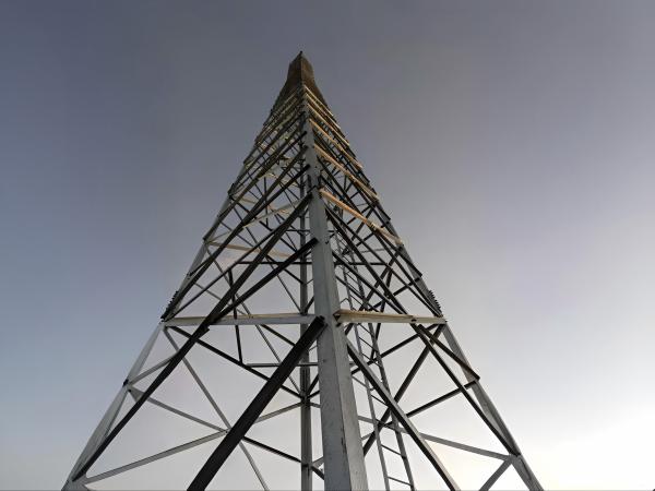
3 leg lattice steel tower


Part 1: The Manufacturing Process – Forging the Backbone

The transformation of raw materials into a structural tower is a symphony of heavy fabrication and meticulous quality control.

1. Material Preparation & Cutting:
The process begins with high-quality low-carbon steel coils. These are uncoiled and leveled before being slit into narrow strips. These strips are then fed through a series of rolls in a cold-forming process to shape them into the standard L-shaped angle profiles. This cold-working increases the strength of the steel through strain hardening.

The long angles are then cut to specific lengths as per the tower design drawings using high-precision saw cutting or shearing. This ensures clean, burr-free ends with exact angles for perfect fit-up during assembly.

2. Punching & Drilling:
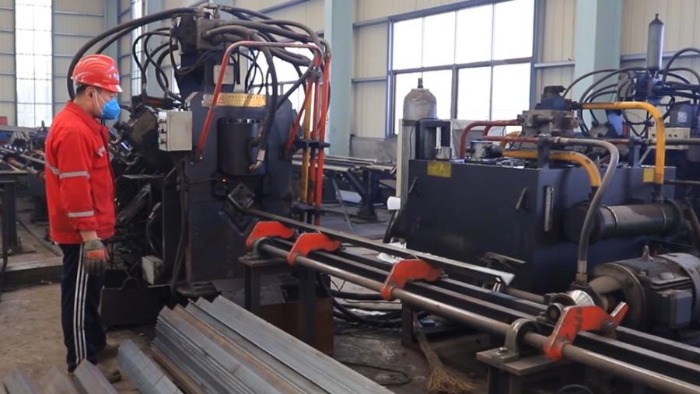
This is a critical step for the tower's bolted connection philosophy. The cut angles are moved to massive CNC (Computer Numerical Control) punching machines. These machines use hydraulic rams and custom dies to punch out the exact pattern of holes for bolts with incredible speed and accuracy. CNC technology ensures that every component is identical, eliminating assembly errors and ensuring structural integrity. Hole edges are deburred to prevent stress concentrations and ensure smooth bolt insertion.

3. Cold Bending & Forming:
For certain components like bracings or curved connections, angles need to be bent. Cold bending is predominantly used, where the steel is formed at room temperature using hydraulic presses or rotary draw benders. It's efficient and preserves the material's properties. For very thick sections or tight radii, hot bending (heating the steel to a specific temperature to make it pliable) might be employed, though it's less common for standard angles.

4. Assembly & Welding (Sub-Assembly):
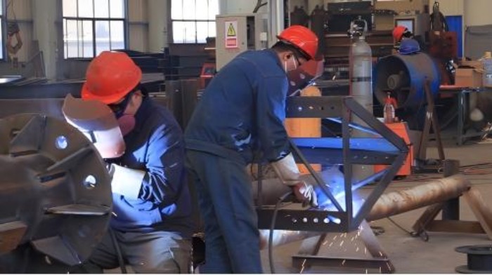
While the primary structure is bolted for ease of transport and field assembly, smaller sub-assemblies like connection plates, stub ends, and ladder supports are welded. Skilled welders use processes like SMAW (Shielded Metal Arc Welding) or more efficient FCAW (Flux-Cored Arc Welding). All welding is performed to strict procedures, and welds are visually inspected and often tested using Non-Destructive Testing (NDT) methods like Magnetic Particle Inspection (MPI) to ensure they are free of cracks and defects.


3 leg lattice steel tower


3 leg lattice steel tower


lattice steel tower


Part 2: The Crown Jewel of Corrosion Protection: Hot-Dip Galvanizing

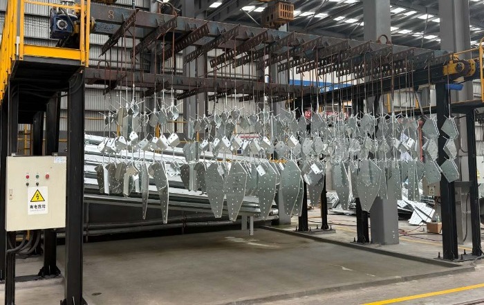
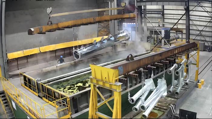
After fabrication, every single component undergoes the most crucial step: hot-dip galvanizing. This process provides a metallurgical bond between zinc and steel, offering superior, long-lasting protection.

The Galvanizing (Process Flow):

  1. Degreasing/Caustic Cleaning: Removes organic contaminants like oil, grease, and dirt.

  2. Pickling (Acid Bath): Immersion in a diluted Hydrochloric or Sulphuric acid solution to remove mill scale and rust, exposing perfectly clean steel.

  3. Fluxing: The components are dipped in a zinc ammonium chloride solution. This flux prevents oxidation before galvanizing and promotes the zinc-steel reaction.

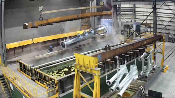
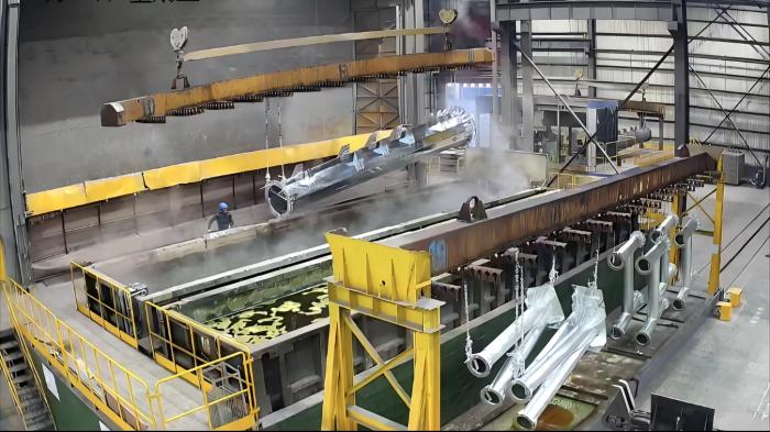
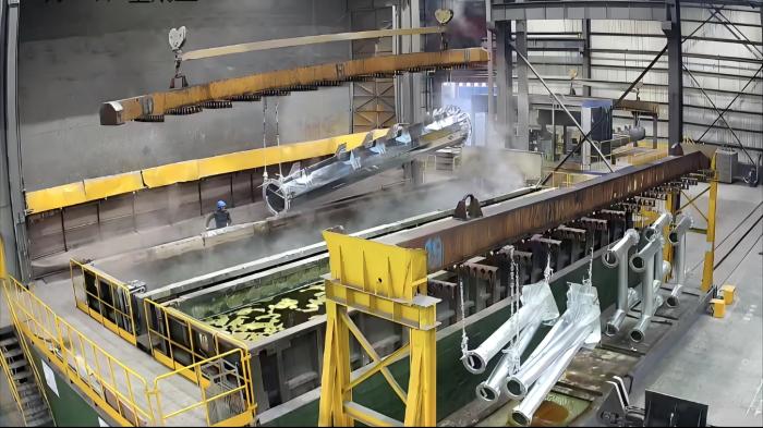
  4. Galvanizing: The dried components are immersed in a bath of molten zinc at around 450°C (840°F). The iron in the steel reacts with the zinc to form a series of zinc-iron alloy layers, topped by a layer of pure zinc.

  5. Quenching: The galvanized parts are slowly withdrawn from the bath and then cooled in a water quench tank to stop the reaction and solidify the coating.

Zinc Thickness Control & Quality Inspection:

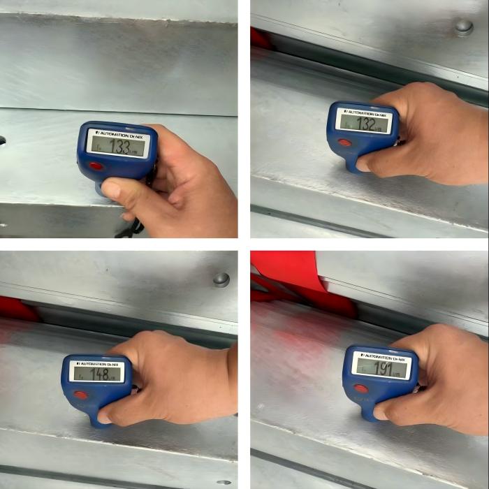
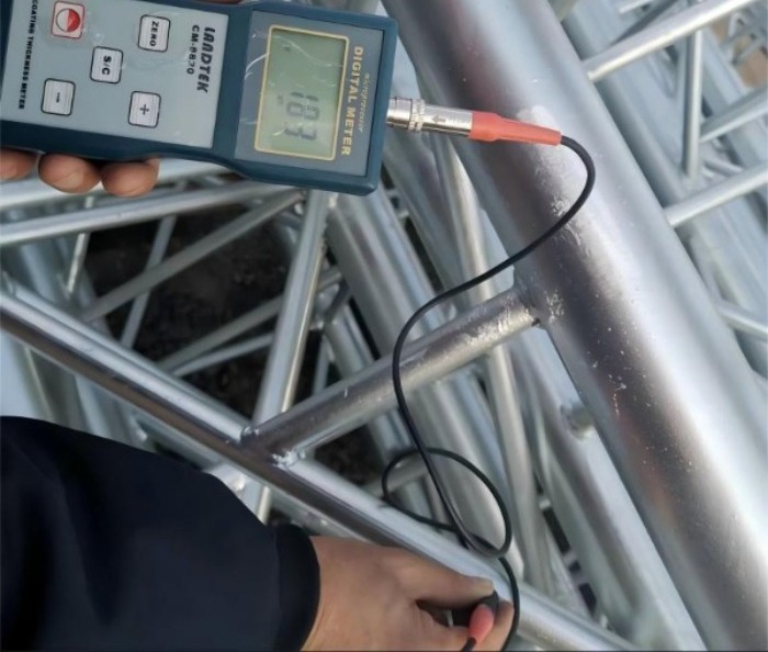
  • Thickness: Standards like ASTM A123 specify minimum coating thicknesses based on material thickness. A typical angle will have an average coating of 85-100 µm (3.5-4 mils). Thickness is verified using magnetic or electromagnetic gauges.

  • Quality: The coating is inspected for uniformity, smoothness, and adhesion. Key tests include the "Preece Test" (copper sulphate dip) for the presence of uncoated spots and a "Quench Test" to check for excessive brittleness.


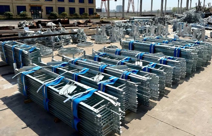
galvanized lattice tower


galvanized lattice steel tower


galvanized lattice steel tower


Part 3: Application & Economics: Choosing the Right Protection

While hot-dip galvanizing is the industry standard for a reason, other options exist for specific scenarios. The choice is a balance of environment and lifecycle cost.

Corrosion Environment Recommended Protection Technical Rationale Lifecycle Cost Analysis
Inland / Rural (C1-C2) Hot-Dip Galvanizing (HDG) Provides cathodic protection (sacrifices itself to protect the steel) and a robust barrier. Low maintenance. Lowest LCC. High initial cost is offset by 40-50+ years of service with zero maintenance. The benchmark for value.
Coastal / High Humidity (C3-C4) HDG or HDG + Duplex System Salt and moisture drastically accelerate corrosion. A Duplex System (HDG followed by a specialized paint) provides enhanced barrier protection and extends service life significantly. HDG alone: Good, may require inspection/repaint later.
Duplex System: Higher initial cost but can extend the maintenance-free period by 1.5-2x, offering excellent long-term value.
Severe Industrial (C4-C5) Duplex System or Specialty Coatings Chemical pollutants (SO₂, NOx) create highly aggressive acids. A thick, chemical-resistant paint layer over the galvanizing is essential. Highest initial cost but the only economically viable long-term solution. Prevents catastrophic failure and constant repairs.
Special Cases (Aesthetics, Touch-up) Paint/Spray Systems (alone) Used only for visual blending in urban areas or for on-site repair of galvanized coating damaged during transport/installation. High LCC. Used only where HDG is not feasible. Requires frequent inspection and recoat cycles (every 5-15 years).

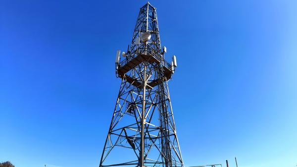
lattice steel cell tower


Conclusion: An Investment in Longevity

The manufacturing and galvanizing of a three-legged angle steel tower is not merely a production line; it's a commitment to quality and longevity. The upfront investment in rigorous fabrication and superior hot-dip galvanizing pays massive dividends over the tower's entire lifecycle, minimizing downtime, eliminating expensive maintenance climbs, and ensuring network reliability for generations. When specifying your next tower project, understanding this process is key to making a smart, technically sound, and ultimately economical decision.


 Learn more at   www.alttower.com


Contact Us

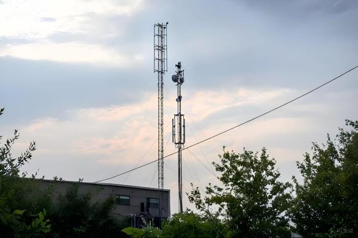
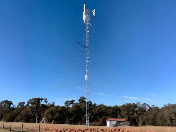
For network planners and infrastructure engineers, few decisions impact project economics as profoundly as tower type selection. Guyed wire towers—supported by high-strength steel cables—offer compelling advantages but come with nuanced trade-offs. As 5 densification accelerates and networks expand into challenging terrain, understanding when and why to deploy guyed structures becomes critical. Let’s dissect the technical and economic logic behind this engineering choice.


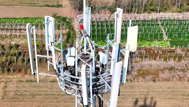
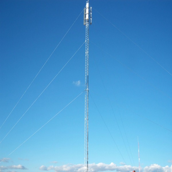
guyed mast antenna tower


1. The Technical Decision Matrix: Where Guyed Towers Excel

(1) Height-Cost Curve Analysis: Defying Gravity Economically

Unlike self-supporting towers whose costs scale exponentially with height, guyed towers maintain a near-linear cost-to-height relationship. This stems from their core design principle:

  • Cables replace steel: Instead of relying solely on structural steel for stability, guyed towers offload wind/ice forces to ground-anchored cables. A 60m guyed monopole can use 40–50% less steel than a self-supporting lattice tower of equal height.

  • Height flexibility: Beyond 45m, guyed configurations become dramatically cheaper. For example:

    1. At 50m, guyed towers cost ≈$28,000 vs. $52,000 for self-supporting alternatives.

    2. At 60m+, savings exceed 50% due to avoided material thickening for buckling resistance.

Table: Cost Per Meter Comparison (USD)

Height Guyed Tower Self-Supporting Tower Savings
30m $900–$1,200 $1,100–$1,400 ~15%
45m $1,400–$1,800 $2,200–$2,800 ~35%
60m $1,800–$2,200 $4,000–$4,500 >50%

(2) Land Footprint Economics: The Hidden Cost Driver

Guyed towers require larger land areas for anchor points (typically 3–4 radial cables spaced 109°–120° apart). However, their economic viability hinges critically on land type:

  1. Low-opportunity-cost land: In deserts, tundra, or rural mountains (e.g., China’s Gobi Desert), land costs are negligible. Here, guyed towers slash total project costs by 30–40%.

  2. Urban/high-value land: Anchor footprints (up to 500m) make guyed towers impractical where real estate is expensive. Self-supporting monopoles with 1–2m² bases dominate cities.

  3. Sloped terrain: Adjustable screw-jack anchors enable installation on slopes ≤35°, avoiding costly site leveling.

(3) Lifecycle Economics: Beyond the Sticker Price

While guyed towers have lower upfront costs, their lifecycle value depends on three operational factors:

  1. Maintenance intensity: Cables require tension monitoring and corrosion protection. In harsh environments, maintenance costs run 15–20% higher than for self-supporting towers.

  2. Longevity: Hot-dip galvanized cables (per ASTM A123) last 50+ years. Combined with replaceable components, guyed towers achieve >40-year service lives with proper upkeep.

  3. Failure resilience: Single-cable failure can collapse the entire tower—making redundancy and ice/wind load overdesign essential in disaster-prone zones.


guyed wire antenna tower


2. Strategic Applications: Where Guyed Towers Deliver Maximum Value

(1) Emerging Market Network Expansion

For rapid rural coverage, guyed towers solve two critical constraints:

  1. Transportation bottlenecks: In mountainous areas like Guangxi, China, traditional 21m towers (97.9 kg/section) required road construction. New lightweight guyed designs (77.46 kg/section) are drone-transportable, cutting deployment time by 7 days/site.

  2. Coverage extension: A 24m guyed tower increases coverage radius by 19% versus a 21m traditional tower, enabling fewer sites per population covered.

(2) Temporary/Emergency Deployments

Guyed towers shine in transient scenarios:

  1. Disaster recovery: Modular designs allow assembly in <72 hours. No concrete foundations are needed—grouted soil anchors suffice for 2–3 year deployments.

  2. Event coverage: For Olympics or festivals, telescoping guyed masts enable height adjustments without crane redeployment.

(3) Tower Sharing Economics

Guyed structures amplify revenue potential in multi-operator models:

  1. High load flexibility: Additional antennas (up to 12/sector) can be added without structural reinforcement.

  2. Revenue stacking: A single guyed tower hosting 3 operators generates ~$1,194/year in lease fees—delivering ROI in 5–7 years.

  3. Shared infrastructure leverage: As seen in China Tower’s model, guyed sites reduce industry-wide capex by $2,100M through co-location efficiency.


3. Decision Framework: Key Selection Criteria

Use this checklist to evaluate guyed tower suitability:

  1. Height requirement ≥45m

  2. Land cost ≤$500/acre (e.g., deserts, grasslands)

  3. Soil type: Non-rocky, anchor-friendly soils (silt, sand, clay)

  4. Wind/ice loads: Wind ≤33 m/s; radial ice ≤15 m

  5. X Space-constrained sites: Urban cores, protected wetlands

  6. X High-vandalism zones: Cable cutting risks

For borderline cases, run a 20-year TCO simulation incorporating:

 
TCO = C_{tower} + C_{land} + \sum_{t=1}^{20} \left( \frac{C_{maintenance} + C_{downtime}}{(1+r)^t} \right)

Where r = discount rate (recommended 5–8%).


guyed wire antenna tower


4. The Future: Smart Guyed Towers

Emerging innovations are enhancing guyed tower viability:

  1. IoT-enabled cables: Embedded strain sensors predict tension loss or corrosion.

  2. Hybrid materials: Carbon-fiber-reinforced cables reduce weight by 20% while increasing strength.

  3. Robotic maintenance: Drones automate anchor inspections in inaccessible terrain.


Conclusion: Balance Through Context

Guyed towers aren’t universally optimal—but where conditions align, they deliver unrivaled cost/height efficiency. They dominate in:

  1. High-altitude rural/remote deployments

  2. Rapidly scalable emerging-market networks

  3. Multi-operator shared infrastructure

As one grid engineer in China’s western deserts noted: “In the Gobi, land is free but steel is expensive. Guyed towers let us redirect 60% of saved capex to grid resilience.”. For your next project, let terrain, height needs, and land economics—not convention—drive the choice.

Industry Insight: In Q1 2025, 78% of new towers >50m in Africa/Southeast Asia were guyed—a 33% YoY increase. Source: TowerXchange Report


 Learn more at   www.alttower.com


Contact Us

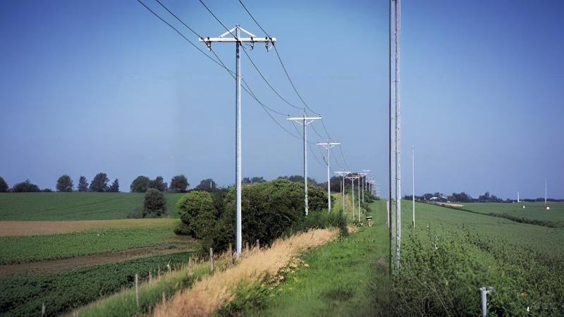
Steel utility poles are rapidly becoming the cornerstone of modern, resilient low-voltage (LV) power distribution networks. Their dominance stems not just from their advantages over concrete, but from sophisticated engineering in their structure, fabrication, and crucially, corrosion protection. Let's delve into the technical heart of these essential grid components.


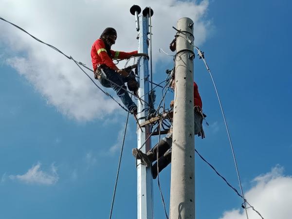
steel utility pole


1. Structural Design: Form Follows Function & Force

LV utility poles are designed to withstand complex loads: vertical weight (conductors, equipment), horizontal wind pressure, and potential ice accumulation. Key structural approaches include:

  1. Tapered Monopoles (Conical): The most common design. The pole diameter and wall thickness gradually decrease from the robust base (high bending moment) to the lighter top. This design:

    1. -Optimizes Material: Uses steel only where strength is needed.

    2. -Improves Aesthetics: Creates a sleek profile.

    3. -Enhances Performance: The conical shape efficiently channels loads to the foundation.

  2. Multi-Section Poles (Combined): Used for very tall poles or specific loading requirements. Sections (usually 2 or 3) are joined together using:

    1. -Flange Connections: Heavy-duty steel plates welded to the ends of each section, bolted together. Requires precise machining and bolting procedures. Offers high strength and rigidity. Common for larger poles.

    2. -Socket (Slip Joint) Connections: The upper section has a reduced diameter end that fits into the lower section. Fixed with through-bolts or shear pins. Faster installation but generally used for lighter loads or shorter heights than flange connections.

  3. Design Principle: The cross-section (diameter, wall thickness) is meticulously calculated based on:

    1. -Section Modulus: Determines the pole's resistance to bending moments caused by wind and conductor loads.

    2. -Moment of Inertia: Influences resistance to buckling.

    3. -Local Buckling Criteria: Ensures the thin steel walls don't buckle under compression.

    4. -Deflection Limits: Ensures the pole doesn't bend excessively under load, maintaining safe conductor clearances.

2. Manufacturing Process: Precision from Plate to Pole

Quality manufacturing is paramount for performance and longevity. The core process involves:

  1. Material Selection & Cutting: High-quality structural steel plates (e.g., ASTM A572 Grade 50) are precisely cut to trapezoidal shapes using CNC plasma or laser cutters.

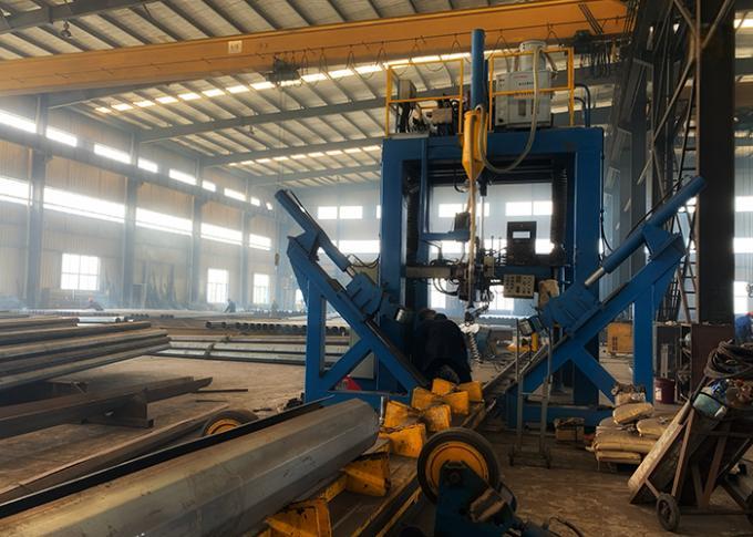
  2. Rolling: The flat plates are fed through a series of rollers in a pyramid rolling machine. Progressive bending transforms the trapezoid into the conical or cylindrical shape. Precision control ensures consistent taper and roundness.

  3. Longitudinal Welding: The rolled plate's edges are brought together and welded along the entire length using Submerged Arc Welding (SAW). SAW is favored for:

    1. -Deep Penetration: Creates a strong, uniform weld through the entire thickness.

    2. -High Deposition Rates: Efficient for long seams.

    3. -Excellent Quality & Consistency: Produces smooth, slag-free welds with minimal spatter under a protective flux layer.

    4. -Critical QC: Weld integrity is non-negotiable. Strict procedures govern pre-heating (if required), weld parameters (voltage, current, speed), and post-weld inspection. Non-Destructive Testing (NDT) like Ultrasonic Testing (UT) or Radiographic Testing (RT) detects internal flaws (porosity, lack of fusion, cracks).

  4. Straightening & Sizing: The welded shell may pass through sizing rolls or be straightened using hydraulic presses to ensure perfect alignment and dimensional accuracy.

  5. End Preparation: Base plates are welded on for direct burial or anchor bolt connection. Top plates or connection hardware (flanges or socket ends) are welded on. Holes for equipment mounting are precisely drilled or punched.

  6. Cleaning & Surface Preparation (Critical for Coating): The pole undergoes rigorous cleaning:

    1. -Degreasing: Removes oils and greases.

    2. -Pickling: Acid bath removes mill scale and rust.

    3. -Fluxing: Applies a protective layer (often zinc ammonium chloride) to prevent oxidation before galvanizing and promote zinc adhesion.


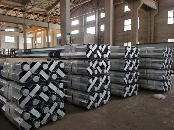
utility steel pole


3. Corrosion Protection: The Lifeline Defense

Protecting steel from the elements is the single most critical factor ensuring decades of service. Two primary systems dominate LV poles:

  • 1. Hot-Dip Galvanizing (HDG): The Gold Standard

    • Process: The meticulously cleaned pole is immersed in a bath of molten zinc (typically ~450°C / 840°F). A metallurgical reaction occurs, forming a series of zinc-iron alloy layers topped by a layer of pure zinc.

    • Key Standards: ASTM A123/A123M is the primary specification in North America for galvanizing structural steel. It dictates:

      1. -Coating Thickness: Minimum requirements based on steel thickness (e.g., for steel >6mm, min avg. thickness is 85µm / 3.4 mils). Thicker steel generally requires/thicker coating.

      2. -Adherence: The coating must withstand specific tests without flaking.

      3. -Appearance: Specifies acceptable surface conditions.

    • Advantages: Exceptionally durable, long-lasting (50+ years typical), provides cathodic (sacrificial) protection to exposed steel edges or scratches, low maintenance.

    • Quality Control: Coating thickness is measured magnetically (e.g., Elcometer) at multiple points. Visual inspection checks for uniformity, lumps, bare spots, and ash inclusions. Adherence is tested by quenching or light hammering.

  • 2. Advanced Coatings (Polymer/Powder Coating):

    1. Process: Applied after galvanizing (Duplex System) or directly onto specially prepared steel (less common for ground-line exposure). Typically involves spraying electrostatically charged powder (epoxy, polyester, polyurethane) onto the pole, which is then cured in an oven, forming a thick, continuous film.

    2. Advantages: Wide range of colors (aesthetics), excellent UV resistance, good chemical resistance, smooth finish. In a duplex system, it adds significant extra lifespan by shielding the zinc layer.

    3. Applications: Increasingly popular, especially for urban areas where aesthetics matter, or combined with HDG for maximum protection. Direct-to-steel coatings require meticulous surface preparation (e.g., abrasive blast cleaning to Sa 2.5 profile) and are generally used for above-ground sections or less corrosive environments than HDG alone.

    4. Standards: ASTM standards like D4138 (adhesion), D3359 (cross-hatch adhesion), D714 (blistering), D4060 (abrasion), D4585 (salt spray) are relevant for testing coating quality.


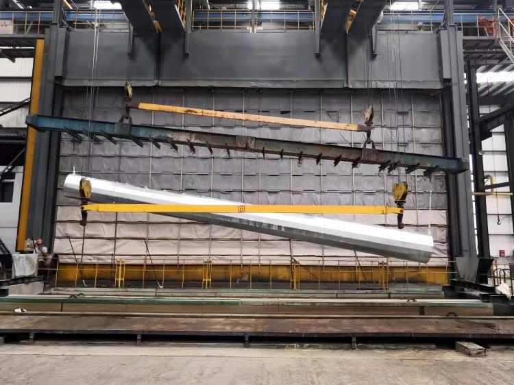
galvanized utility pole


Conclusion: Engineering Excellence for Grid Resilience

The widespread adoption of steel tubular poles in LV networks is built upon a foundation of sophisticated structural engineering, precision manufacturing – particularly high-integrity welding – and, most critically, advanced, rigorously controlled corrosion protection systems. Understanding the interplay between the tapered or multi-section design, the robust manufacturing process with its emphasis on weld quality, and the science behind coatings like hot-dip galvanizing (governed by standards like ASTM A123) reveals why these poles offer superior longevity, reliability, and lifecycle value. As grids face increasing demands from urbanization and extreme weather, the technical excellence embedded in the design, fabrication, and corrosion defense of steel tubular poles ensures they will remain a vital part of our power infrastructure for decades to come. 


 Learn more at   www.alttower.com


Contact Us 

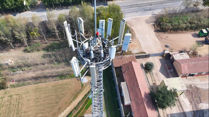
The promise of 5G is dazzling: blistering speeds, massive device connectivity, and ultra-low latency. At the heart of delivering this, especially for capacity-hungry urban and suburban areas, lies massive MIMO (mMIMO) technology. These advanced antenna arrays, packing 32, 64, or even more elements, aren't just bigger antennas – they're sophisticated beamforming engines. But their performance hinges critically on one often-overlooked factor: the tower they sit on. Forget the "dumb steel pole" mindset. When deploying mMIMO, the inherent design of tubular steel towers unlocks significant RF advantages that concrete or lattice structures simply can't match.


tubular steel tower


1. Precision Placement & Rigidity: The Foundation of Beamforming

  • The Challenge: mMIMO relies on precise phase relationships between its many radiating elements to electronically steer focused beams towards users. Any unwanted movement, vibration, or distortion of the antenna platform degrades beamforming accuracy, reducing signal strength, increasing interference, and lowering network capacity.

  • The Tubular Advantage:

    1. Inherent Rigidity: The continuous, closed cross-section of a tubular steel monopole provides exceptional torsional and lateral stiffness. This minimizes deflection caused by wind, reducing antenna sway and micro-vibrations that disrupt beam patterns.

    2. Precise Mounting Surfaces: Modern tubular towers feature precisely engineered mounting interfaces (e.g., welded mounting plates, specialized brackets). This allows for millimeter-accurate positioning and levelling of heavy mMIMO panels, ensuring the antenna array itself is perfectly planar and stable.

    3. Reduced Structural "Noise": Unlike lattice towers with numerous joints and potential points of flex, the smooth, continuous surface of a tubular tower provides a predictably stable platform, minimizing unpredictable structural movements that confuse beamforming algorithms.

2. Optimized Mounting Geometry: Unlocking mMIMO's Potential

  • The Challenge: mMIMO arrays require specific spatial configurations for optimal performance. Elements need consistent spacing (often λ/2, where λ is the wavelength) and must be positioned to minimize mutual coupling and pattern distortion. Mounting on irregular or obstructive structures severely hampers this.

  • The Tubular Advantage:

    1. Clean Cylindrical Profile: The smooth, unobstructed surface of a tubular tower provides an ideal backdrop. Antennas mount flush against the curve, minimizing scattering and reflections that can distort radiation patterns and create unintended sidelobes.

    2. Predictable Near-Field Environment: The uniform curvature and lack of sharp edges/cross-braces create a predictable electromagnetic near-field environment around the antennas. This is crucial for accurate beamforming calculations and minimizing pattern distortion compared to the complex scattering environment of a lattice tower.

    3. Flexible Array Orientation: Tubular towers readily accommodate mounting mMIMO panels in the optimal orientation (e.g., vertical or slightly downtilted columns) without structural interference, maintaining consistent element spacing across the array.


tubular steel telecom tower


3. Enabling Colocation & Future-Proofing: Density Without Compromise

  • The Challenge: 5G densification requires packing more sites, often with multiple operators and technologies sharing infrastructure. mMIMO panels are large and heavy. Traditional structures can become cluttered, leading to antenna coupling, blocking, and complex installation challenges.

  • The Tubular Advantage:

    1. Aerodynamic Efficiency: The sleek, tapered design minimizes wind loading per unit height. This allows tubular towers to be built taller than similarly rated lattice structures, creating more usable vertical real estate.

    2. 360-Degree Mounting Potential: The continuous cylindrical surface provides ample, obstruction-free space around the entire circumference. This allows for the strategic placement of multiple mMIMO panels (potentially for different operators or frequency bands) at optimal heights and azimuths without significant mutual blockage or coupling.

    3. Structural Headroom: Designed with significant load margins, modern tubular towers easily accommodate the weight and wind load of multiple large mMIMO panels, plus future additions like mmWave radios or additional arrays, simplifying network evolution.

4. Aesthetics Meets RF Performance: The Hidden Link

  • The Challenge: Municipalities demand low visual impact, especially in dense urban or scenic areas. Bulky lattice towers or large concrete bases are often visually unacceptable. RF performance shouldn't suffer due to aesthetics.

  • The Tubular Advantage:

    1. Sleek, Minimalist Profile: The slender, monopole design has the smallest possible visual footprint, making it the preferred choice for restrictive zoning areas. This isn't just about looks; it means towers get approved and deployed where needed most.

    2. No RF Sacrifice: Crucially, achieving this aesthetic acceptance does not come at the cost of RF performance. The structural and mounting advantages inherent to the tubular design are maintained, ensuring mMIMO can perform optimally even on the most discreet structures. The visual benefit is a direct enabler of optimal RF site placement.


tubular lattice tower


Specification is Key: Maximizing the mMIMO Advantage on Tubular Towers

To fully leverage these RF benefits, precise specification is essential:

  1. Demand High Rigidity: Specify deflection limits under wind load relevant to mMIMO stability (e.g., top deflection < height/200 for operational winds).

  2. Precision Mounting Systems: Require engineered mounting solutions (plates, brackets) designed for specific mMIMO panel weights, dimensions, and mounting patterns, ensuring perfect levelling and stability.

  3. Corrosion Protection: Specify robust systems like Zn-5%Al coating and cathodic protection (as highlighted in our coastal article) to ensure long-term structural integrity and prevent rust-induced distortions or mounting point failures.

  4. Adequate Height & Diameter: Ensure sufficient tower height for clear RF pathways and a base diameter large enough to provide stable mounting real estate for current and future mMIMO arrays.

  5. Professional Installation: Mandate certified installers using calibrated equipment to guarantee precise antenna positioning and alignment according to the tower manufacturer's specifications.

Conclusion: The Intelligent Foundation for Intelligent Networks

Deploying 5G mMIMO isn't just about bolting on advanced antennas; it's about creating the optimal electromagnetic environment for them to perform. Tubular steel towers are far more than passive supports. Their inherent rigidity, clean electromagnetic profile, flexible mounting real estate, and aesthetic acceptance make them the engineered foundation for unlocking the full potential of mMIMO beamforming. By understanding and specifying for these "beyond the surface" RF optimization secrets, network operators can build higher-performing, more reliable, and future-proof 5G networks that truly deliver on the promise. Don't let your tower be the weakest link in your mMIMO strategy.


Contact Altai for Custom Designs:
attower88@gmail.com | |

For power utilities battling corrosion in coastal, industrial, and high-humidity zones, breakthroughs in hot-dip galvanizing (HDG) technology now enable 33kV steel transmission poles to achieve 50+ year lifespans – slashing replacement costs by 300% versus traditional methods. Here’s the science making this possible:


33kv utility pole


The Corrosion Challenge in Energy Infrastructure

33kV poles face relentless degradation from:

  1. Salt Spray: Coastal sites lose 25µm/year vs. 4µm inland

  2. Chemical Exposure: Industrial SO₂/NOx accelerates rust 5x

  3. Galvanic Corrosion: Dissimilar metal contacts (e.g., Cu earth wires)

  4. Microbiologically Influenced Corrosion (MIC): Soil-bound bacteria at base

Conventional paint systems fail in 12–15 years, triggering costly rebuilds.


Breakthrough 1: Next-Gen Hot-Dip Galvanizing

Process Innovations

Technology Traditional HDG Advanced HDG Impact
Pre-Treatment Acid pickling Abrasive blasting + Nanocoat Removes 100% mill scale
Zinc Bath Chemistry 99.995% Zn Zn-5%Al-0.1%Ni (Galfan) 2x salt resistance vs. pure Zn
Immersion Control Manual timing Magnetic flux-guided robotics Coating uniformity ±5µm
Quenching Water spray Chromate-free passivation Eliminates toxic hexavalent Cr

Performance Data (ISO 9227 Salt Spray)

plaintext
 
Coating Type        | Hours to Red Rust | Equivalent Field Life  
----------------------------------------------------------  
Standard Paint      | 1,000h            | 10-12 years  
Pure Zinc HDG       | 3,500h            | 25-30 years  
Galfan HDG          | 8,000h            | 50+ years  

Breakthrough 2: Multi-Layer Defense System

Hybrid Protection for Critical Zones

plaintext
 
[Pole Zone]        [Protection Stack]                          [Lifespan]  
-----------------------------------------------------------------------  
**Upper Mast**     • 120µm Galfan HDG                          50+ years  
                   • UV-stable silicone topcoat (RAL 7016)  
  

Ground Contact • 300µm Zn-Al thermal spray Lifetime
• HDPE sacrificial sleeve + cathodic protection

Bolt Interfaces• Stainless steel (A4-80) + dielectric gel 60 years


33kv utility steel pole

utility steel pole

Breakthrough 3: Digital Lifecycle Management

IoT-Driven Predictive Maintenance


Proven Field Performance

Case 1: Norwegian Coastal Grid

  1. Environment: North Sea salt spray + -30°C freeze-thaw

  2. Solution: Galfan HDG + thermal-sprayed base

  3. Result: 0% failure at 32-year inspection (projected 60-year life)

Case 2: Guangdong Industrial Zone

  1. Challenge: Acid rain (pH 4.2) + 90% humidity

  2. Solution: Zn-Ni HDG (200µm) + conductive polymer topcoat

  3. Result: 5µm corrosion loss after 15 years (vs. 80µm predicted)


Lifecycle Cost Advantage

Corrosion System Initial Cost 50-Year Cost Savings vs. Paint
Epoxy Paint $12,000 $48,000 Baseline
Pure Zinc HDG $18,000 $36,000 25%
Galfan HDG Hybrid $23,000 $26,500 45%
Based on 100 poles, NPV @ 5% discount rate

11kv utility steel pole


The Future: Smart Coatings


*"After Cyclone Gabrielle destroyed painted poles in New Zealand, our Galfan-treated 33kV structures survived with only 3µm coating loss. This technology is rewriting infrastructure economics."*
– Dr. James Chen, Grid Resilience Director, Transpower NZ


 Learn more at   www.alttower.com


Contact Us  

Here is a detailed technical and commercial introduction to Aluminum Alloy Telecommunication Lattice Towers, incorporating engineering innovations, comparative advantages, and real-world applications:


aluminum lattice tower


Aluminum Alloy Telecommunication Lattice Towers: The Next-Gen Infrastructure Solution

Engineered for Durability, Speed & Sustainability

I. Core Material & Structural Advantages

  1. Advanced Aluminum Alloy (6061-T6)

    • Compliance: ASTM B221/B241, EN 573-3

    • Strength-to-Weight Ratio: 40% lighter than steel equivalents while maintaining equivalent load capacity.

    • Corrosion Resistance:

      • Natural oxide layer + anodizing/powder coating.

      • Salt spray resistance >2,000 hours (ASTM B117).

      • Zero rust maintenance, ideal for coastal, industrial, or high-humidity zones.

  2. Lattice Geometry Optimization

    • Triangular Configuration: Maximizes torsional rigidity and wind load dissipation.

    • Modular Design:

      • Pre-fabricated bolted sections (4–6m lengths).

      • Rapid assembly with standard tools (50% faster vs. steel).


II. Technical Specifications

Parameter Specification
Height Range 15m – 120m (Customizable)
Wind Load Capacity 55 m/s (200 km/h) with antennas
Ice Load 30mm radial ice (ISO 12494)
Seismic Performance Zone 5 (IBC 2018)
Foundation Shallow concrete/base plates (50% less excavation)
Design Life 30+ years (zero structural maintenance)

III. Engineering Innovations

  1. Patented Joint System

    1. Compression Connectors (Patent ZL202310XXXXXX):

      1. Eliminates bolts → no corrosion points or loosening risks.

      2. 20% faster assembly vs. traditional bolted joints.

  2. Smart Integration Features

    1. Cable Management: Internal conduit pathways (IP67 sealed).

    2. 5G/6G Readiness:

      1. mmWave antenna mounts (up to 200kg/sector).

      2. Grounding system (≤5Ω resistance, IEC 62305).

  3. Extreme Environment Adaptability

    1. Arctic: Anti-icing alloy treatment (-40°C operation).

    2. Desert: UV-reflective coating (120°C tolerance).

    3. Marine: Marine-grade anodizing (ISO 12944 C5-M).


aluminum alloy tower


IV. Performance vs. Steel Lattice Towers

Metric Aluminum Lattice Steel Lattice
Weight (45m tower) 1,400 kg 2,600 kg
Installation Time 2 days (6 crew) 4–6 days
Lifetime Maintenance Cost $0 (no repainting) $15K+/decade (galvanization renewal)
Carbon Footprint (30y) 8.2 tons CO2e 22.1 tons CO2e
Recyclability 100% (no downgrading) 60–70%

V. Real-World Applications & Case Studies

  1. Urban 5G Densification (Barcelona, Spain)

    • Project: 28x 30m towers for street-level small-cell aggregation.

    • Results:

      • 3-day installation per tower (minimal traffic disruption).

      • 25% TCO savings over 10 years vs. steel.

  2. Typhoon-Resilient Network (Okinawa, Japan)

    • Challenge: Steel towers corroded within 5 years in coastal climate.

    • Solution: 18x 60m aluminum lattice towers with seismic bracing.

    • Outcome: Zero maintenance after 8 years; survived 240 km/h winds (2022).

  3. Eco-Sensitive Deployment (Maldives Islands)

    • Requirement: Low-weight towers for coral-reef foundation limits.

    • Altai’s Answer: 45m aluminum lattice on micro-piles (no concrete).

    • Impact: 60% less site disturbance; 100% tower recyclability.


VI. Why Choose Altai’s Aluminum Lattice Towers?

End-to-End Customization:

“Aluminum lattice towers aren’t just lightweight – they’re a total ecosystem solution: reducing installation carbon footprint by 63%, eliminating lifetime maintenance, and accelerating ROI.”
― Altai Engineering Group


aluma telecom tower 


VII. Ideal Use Cases

Scenario Benefit
Rapid network expansion 50% faster deployment vs. monopole/steel
Mountainous/remote terrain Helicopter-transportable modules
Temporary events (Olympics) Reusable towers; 1-day teardown
Greenfield 6G rollout Future-proof antenna mounting system


Tags:aluminum alloy telecom tower, aluminum tower, aluminum lattice tower


Contact Altai for Custom Designs:
attower88@gmail.com |


The Physics of Stability
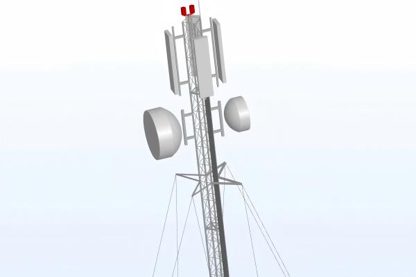
While self-supporting towers rely on rigid foundations to resist wind loads, guyed mast towers leverage a triangular tension system to achieve unparalleled stability:

  1. Dynamic Load Distribution: Guy wires convert lateral wind forces (up to 150 km/h) into vertical tension, reducing tower shaft stress by 60% versus self-supporting designs.

  2. Anti-Overturning Mechanism: Each wire anchor acts as a pivot point, creating counter-moments that neutralize torsion during storms. At 40m height, a 3-anchor system provides 360° load balancing with just 25% steel usage of lattice towers.


guyed wire telecom tower


Wind Load Performance Comparison

Tower Type Max Wind Resistance Material Cost Foundation Depth
Self-Supporting 130 km/h $28,000 3.5m
Guyed Tower 150 km/h $11,200 1.2m

(Data: ITU-R F.1507 standards / Huawei rural deployment cases)


UHF Coverage Scenarios: Where Guyed Towers Win

1. Rural Blanket Coverage (e.g., Indian Plains)

  1. 100km² Coverage per Tower: 40m guyed towers achieve 45dB UHF signal strength across flat terrain using 700MHz band.

  2. Cost Efficiency: Nigeria's Phase III National Broadband Plan deployed 12,000 guyed towers at $9.3k/unit – 58% cheaper than alternatives.

2. Mountainous Signal Relay (e.g., Peruvian Andes)

  1. Slope Adaptability: Guy anchors secure to bedrock at 30° inclines where concrete foundations fail.

  2. Signal Hopping: Chile's ENTEL uses cascaded guyed towers (15km spacing) to penetrate canyons, achieving 94% 4G availability in remote villages.

3. Disaster-Prone Economies (e.g., Indonesian Islands)

  1. Typhoon Resilience: After 2021 Cyclone Seroja, Timor-Leste's guyed-tower networks suffered <8% downtime vs 67% for monopoles.

  2. Rapid Deployment: Philippine's emergency comms units erect 30m towers in 4 hours using helicopter-transportable kits.


guyed mast telecom tower


The Cost-Sensitive Advantage

Bangladesh's "Digital Island" project demonstrates operational savings:

math
 
\begin{align*}  
\text{Total Cost of Ownership} &= \text{CapEx} + 10\text{-year OpEx} \\  
\text{Self-supporting} &= \$43k + \$96k = \$139k \\  
\text{Guyed Tower} &= \$17k + \$31k = \color{green}{\$48k}  
\end{align*}  

Savings enable 3x more sites per budget – critical for universal service obligations.

When Guyed Towers Aren't Ideal

  1. Urban Microcells: Land constraints make anchor footprints (20m dia.) impractical

  2. Multi-Operator Sites: Limited top-platform space struggles beyond 6 antennas

  3. Vandalism-Prone Areas: Exposed guy wires require tamper-proof monitoring


The Verdict
Guyed towers aren't just "cheap" – they're strategically optimized for UHF's long-range physics. By marrying tensile efficiency with terrain flexibility, they deliver coverage where traditional towers can't compete. As 5G expands into unserved territories, these unsung heroes will remain the backbone of inclusive connectivity.

For project planners: Prioritize hot-dip galvanized steel (ISO 1461) and helical screw anchors in sandy soils. Always budget for tension monitoring systems – loose guys cause 73% of failures.


 Learn more at   www.alttower.com


Contact Us 

When Concrete Fails: Why Tubular Steel Towers Dominate Salite Coastal Sites

Concrete: the seemingly indestructible backbone of modern infrastructure. Yet, place it on a saline coast, and a silent war begins. Salt-laden air and moisture penetrate pores, triggering corrosion of the embedded steel rebar. This rust expands, cracking the concrete from within – a process called spalling. What looks solid becomes dangerously compromised, often with little external warning until catastrophic failure looms. In the relentless battle against coastal corrosion, concrete has a critical vulnerability.


tubular steel tower


This is precisely why tubular steel towers, armed with advanced protection systems, are becoming the undisputed champions for critical structures like telecom towers in these harsh environments. Let's break down their winning defenses:

The Zn-5%Al Alloy Coating: The First Line of Defense

    • What it is: A metallic coating consisting of 95% Zinc and 5% Aluminum, often applied via hot-dip galvanizing to tubular steel sections.

    • Why it wins vs. Salt:

      • Barrier Protection: Creates a dense, continuous physical barrier shielding the underlying steel.

      • Galvanic Sacrifice: Zinc preferentially corrodes, protecting the steel (like standard galvanizing).

      • Aluminum's Superpower: Aluminum forms stable, highly adherent oxide layers (Al₂O₃) that significantly slow down the corrosion reaction itself. This is crucial against the constant chemical assault of chlorides.

      • Self-Healing Potential: The Zn-Al alloy offers better "flow" during application and potentially better healing of minor scratches than pure zinc coatings.

      • Longevity: Zn-5%Al coatings demonstrably outperform standard zinc coatings (Zn-100%) in saline atmospheres, offering significantly extended service life before maintenance is needed. Studies show life extensions of 50-100% or more compared to traditional galvanizing in marine settings.

  1. Cathodic Protection (CP): The Active Shield

    • What it is: An electrochemical technique that forces the entire steel structure to become the cathode in a corrosion cell, halting the corrosion reaction.

    • How it Works with Towers:

      1. Sacrificial Anodes: Blocks of a more reactive metal (like Zinc or Magnesium alloys) are attached directly to the tower's foundation or lower sections. These anodes corrode sacrificially instead of the steel. The Zn-5%Al coating acts synergistically, becoming part of this protective system.

      2. Impressed Current CP (ICCP): For very large or critical structures, a low DC current is applied from an external power source through inert anodes, actively polarizing the steel to a protective state.

    • Why it Wins vs. Salt: CP is highly effective in electrolyte-rich environments like damp, saline soil or splash zones. It provides active, ongoing protection, even if the primary coating is locally damaged. It's the essential "insurance policy" for decades-long durability.


tubular steel tower


tubular steel tower

The Cost of Concrete Failure: Lessons from the Coastlines

  • The Philippines: Tropical storms combined with pervasive salt spray create a nightmare for infrastructure. Numerous concrete telecom tower bases, especially older or less well-maintained ones, suffer severe spalling and rebar corrosion. This leads to:

    1. Emergency structural repairs or rebuilds, causing significant network downtime.

    2. Skyrocketing long-term maintenance costs as patchwork fixes struggle against relentless decay.

    3. Safety hazards from falling concrete chunks or potential structural collapse.

  • The Middle East: While often drier, the combination of extreme coastal humidity, high temperatures accelerating chemical reactions, and frequent sandstorms (abrading surfaces) creates a uniquely aggressive environment. Corrosion rates on unprotected or poorly protected steel and concrete can be shockingly high. Premature degradation of concrete foundations supporting various structures is a well-documented, costly issue.

Tubular Steel: Engineered for Victory

Beyond superior corrosion protection, tubular steel towers offer inherent advantages perfectly suited for challenging coastal deployments:

  1. Strength-to-Weight Ratio: Steel provides immense strength with less bulk compared to concrete. This allows for taller, more slender structures capable of handling heavy antenna loads and high winds.

  2. Design Efficiency: The smooth, tapered profile (like conical monopoles) offers minimal wind resistance.

  3. Foundation Flexibility: Requires significantly smaller, less invasive foundations than heavy concrete structures, crucial for unstable coastal soils or sensitive environments.

  4. Aesthetics & Space Saving: The sleek design drastically reduces visual impact and physical footprint.


tubular steel tower


Proof in Performance: The Dubai Waterfront Advantage

Consider this compelling real-world validation from a demanding coastal megaproject:

"Dubai's ambitious waterfront development faced the dual challenge of harsh salt-laden winds and premium land costs. By deploying tapered tubular steel monopoles (diameter tapering from 1.2m at the base to 0.4m at the top) protected with Zn-5%Al coatings and integrated cathodic protection systems, the project achieved remarkable outcomes vs. traditional lattice (angle steel) towers:

  1. 40% Increase in Wind Load Resistance: The inherent strength and aerodynamic efficiency of the tubular design handled coastal gusts far more effectively.

  2. 70% Reduction in Visual Footprint: The sleek monopoles blended into the upscale waterfront environment, a critical planning approval factor.

  3. $2.8 Million Saved in Land Costs: The drastically smaller base footprint allowed colocation of 12 different operators' equipment on single, efficient towers, avoiding the need for multiple large tower plots on extremely valuable land."**

tubular steel tower

The Verdict for Saline Sites

Concrete's hidden vulnerability to chloride attack makes it a risky long-term proposition for critical coastal infrastructure like telecommunication towers. The combination of advanced metallic coatings (Zn-5%Al) and robust cathodic protection transforms tubular steel towers into the corrosion-resistant champions of these demanding environments. They deliver not just superior durability and safety, but also tangible benefits in performance, space utilization, aesthetics, and ultimately, significant cost savings over the asset's lifetime.

When failure isn't an option on the salty coast, the choice is clear: engineered tubular steel stands tall. Specify Zn-5%Al and CP – it's the investment that withstands the elements.


 Learn more at   www.alttower.com


Contact Us 

keyboard_arrow_up