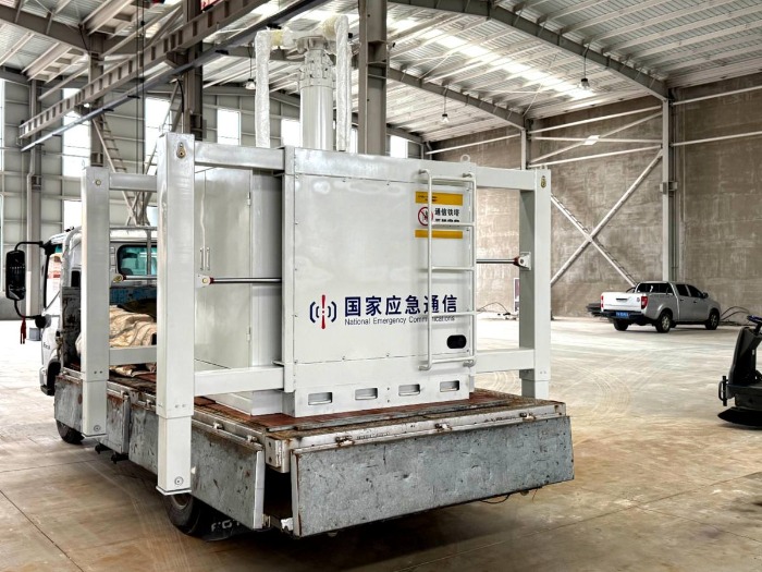
Introduction

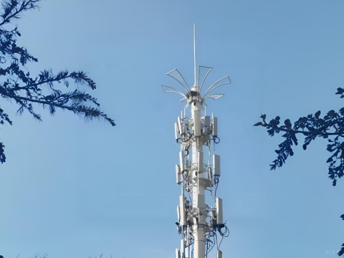
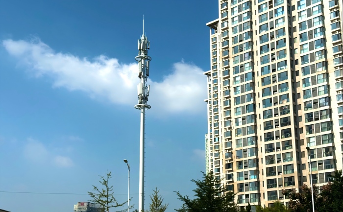
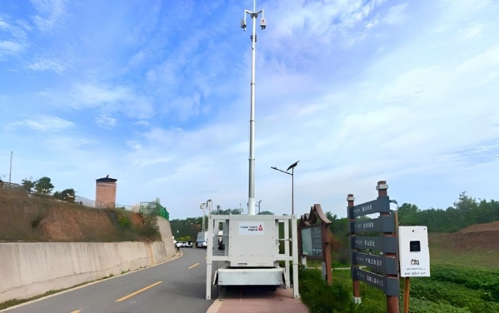
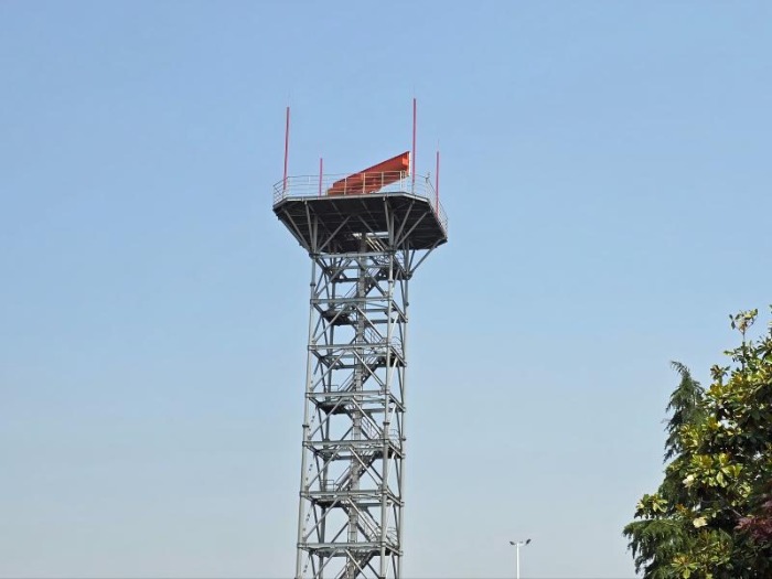
Critical infrastructure demands unparalleled reliability, and nowhere is this more crucial than for radar towers safeguarding aviation, maritime, and national security. These towers are strategically positioned in the most corrosive environments imaginable—exposed coastal zones where salt-laden air, high humidity, and intense UV radiation relentlessly attack structural steel. Ensuring their decades-long service life requires a deliberate, engineered approach to corrosion protection. This blog delves into the advanced defense strategies, centered on Hot-Dip Galvanizing (HDG) and specialized coating systems, that protect these vital assets.


radar mounts


1. The Unforgiving Enemy: Corrosion in Coastal Zones

The corrosion rate for steel in a marine environment can be 3 to 5 times faster than in a rural setting. The primary aggressors are:

  1. · Salt Aerosols: Airborne chloride particles deposit on surfaces, forming a highly conductive electrolyte that accelerates electrochemical corrosion.

  2. · High Humidity: Constant moisture facilitates the corrosion reaction, preventing protective films from forming.

  3. · Cyclic Conditions: Daily temperature and humidity fluctuations cause "breathing," which can drive salt and moisture into micro-cracks.

  4. · UV Degradation: Sunlight breaks down many organic polymer coatings, causing chalking, fading, and loss of film integrity.

For a radar tower, structural failure is not an option. The corrosion protection system must be designed from the outset for ultra-long-term performance with minimal maintenance.


2. The First Line of Defense: Robust Hot-Dip Galvanizing (HDG)

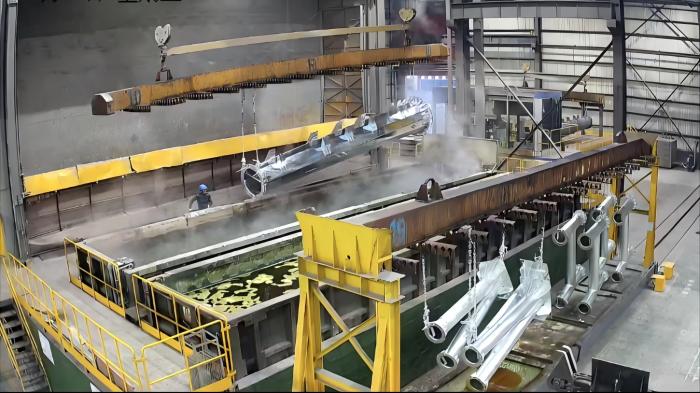
Hot-dip galvanizing forms the foundational, metallurgically-bonded barrier for the entire steel structure. For coastal zones, standard HDG is not enough; an enhanced process is required.

  • · The Process: The fabricated steel is immersed in a bath of molten zinc at around 450°C (840°F). This creates a coating comprised of a series of zinc-iron alloy layers, topped by a layer of pure zinc.

  • · Enhanced Specifications for Coastal Use:

    1. Increased Coating Thickness: We specify coatings that exceed standard requirements. For steel over 5mm thick, a minimum average thickness of 100-120 µm is targeted, in accordance with the most severe service categories of ISO 1461 (e.g., Category 4/5).

    2. Superior Surface Preparation: To ensure perfect adhesion, steel undergoes rigorous cleaning (degreasing, pickling) and fluxing. The quality of this preparation directly dictates the quality and longevity of the zinc coating.

    3. Controlled Withdrawal: The speed and angle at which the steel is withdrawn from the zinc bath are controlled to ensure a uniform, consistent coating, even on complex fabrications.

The HDG layer provides triple protection: a tough physical barrier, cathodic protection (where the zinc sacrificially corrodes to protect the underlying steel), and the unique ability to "heal" minor scratches through galvanic action.


galvanized radar support


3. The Secondary Shield: High-Performance Coating Systems

While HDG is exceptionally durable, adding a specialized coating system creates a synergistic "duplex system" that dramatically extends the service life of both the galvanizing and the coating.

  • · The Synergy of a Duplex System: The HDG layer prevents under-coating corrosion, which is the primary failure mode for paints. Simultaneously, the topcoat shields the zinc from direct exposure to the environment, significantly slowing its consumption rate. The combined system can offer 1.5 to 2.5 times the service life of either system alone.

  • · Coating Selection for Marine Atmospheres:

    1. Epoxy Primers: These are chemically resistant and provide excellent adhesion to the galvanized surface, which must be lightly sweep-blasted or treated with a T-Wash (etching primer) to ensure proper bonding.

    2. Polyurethane Topcoats: Chosen for their outstanding UV resistance, color and gloss retention, and superior weatherability. Aliphatic polyurethanes are the industry standard for a durable, flexible, and chemically resistant finish.

    3. Advanced Resin Systems (e.g., Polysiloxanes): For the most demanding applications, polysiloxane hybrids offer even better UV and corrosion resistance than polyurethanes, with higher dry film thickness (DFT) application in a single coat and superior durability.


weather radar support


4. A Cohesive, Long-Life Protection Strategy

The effectiveness of this defense lies in the integration of all components:

  1. · Design for Durability: The tower's design itself must avoid moisture traps, ensure good drainage, and provide adequate access for future inspection and maintenance.

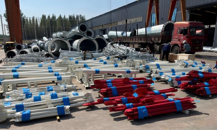
  2. · Rigorous Quality Control: Every step—from surface preparation and HDG bath chemistry to coating DFT verification (measured with magnetic gauges) and adhesion testing—is meticulously controlled and documented.

  3. · Lifecycle Cost Advantage: While the initial investment in an HDG-plus-coating duplex system is higher, the dramatic reduction in maintenance, repainting, and risk of failure makes it the most cost-effective solution over the asset's entire lifecycle.


Conclusion

Protecting critical radar infrastructure in coastal zones is a battle fought with advanced materials science and precise engineering. By deploying a synergistic defense of thick, high-quality hot-dip galvanizing as a robust base, enhanced by a high-performance coating system tailored to withstand salt, sun, and moisture, we can ensure these vital towers stand guard reliably for decades. This multi-faceted approach to corrosion defense is not an expense; it is an essential investment in the resilience and security of our national critical infrastructure.


 Learn more at  www.alttower.com


Contact Us

Introduction

In the world of critical radar infrastructure, precision is everything. Modern radar systems, whether for meteorological monitoring, air traffic control, or defense, demand an exceptionally stable platform. Even minute structural vibrations or sway in a radar tower can introduce phase errors, distort beam patterns, and degrade data quality, leading to a phenomenon known as "structural interference." Achieving zero interference is, therefore, not an aspirational goal but a fundamental engineering requirement. This blog delves into the sophisticated design principles and technologies employed to ensure that the tower itself remains an invisible, stable host for the sensitive equipment it carries.


radar tower for sale


1. The Enemy of Precision: Sources of Vibration and Sway

A radar tower is a dynamic structure constantly subjected to forces that induce motion. The primary culprits are:

  1. Wind Loading: The most significant and persistent force. It creates both static push (mean deflection) and dynamic excitation from vortex shedding and buffeting, leading to resonant vibrations.

  2. Vortex Shedding: As wind flows past the tower, it creates alternating vortices that detach from either side, generating a periodic lateral force. If this frequency aligns with the structure's natural frequency, it can cause significant, sustained vibration.

  3. Equipment-Induced Vibration: The rotation of the antenna and the operation of internal machinery can transmit low-amplitude, high-frequency vibrations through the structure.

  4. Seismic and Environmental Loads: In certain regions, seismic activity and thermal expansion/contraction can also contribute to structural movement.

The consequence of these movements is a deviation in the radar's pointing angle, which can manifest as blurred imagery, inaccurate target tracking, and reduced resolution.


radar tower for sale


2. Foundation of Stability: Dynamic Characteristic Analysis

The first and most critical step in designing for stability is a comprehensive Dynamic Characteristic Analysis. This involves creating a detailed finite element model (FEM) of the entire structure to predict its behavior under dynamic loads.

  1. Natural Frequency and Mode Shapes: Engineers calculate the tower's fundamental natural frequencies and their corresponding mode shapes (the pattern of deformation during vibration). The primary design objective is to tune these frequencies away from the dominant forcing frequencies of the wind (vortex shedding) and the rotating radar antenna.

  2. Wind Tunnel Testing: For critical applications, scale models of the tower are tested in wind tunnels. This validates the computational models and provides precise data on wind forces, including the critical wind speeds that trigger vortex-induced vibrations (VIV).

  3. Aeroelastic Analysis: This advanced simulation assesses the interaction between inertial, elastic, and aerodynamic forces to predict complex phenomena like galloping and flutter, ensuring stability across the entire operational wind speed range.


3. Taming the Motion: The Application of Dampers

Knowing the dynamic characteristics allows engineers to implement targeted solutions to dissipate vibrational energy. Dampers are the key active components in this defense.

  1. Tuned Mass Dampers (TMDs): A TMD is a passive device consisting of a mass, springs, and a damper that is precisely "tuned" to a specific problematic frequency of the tower. When the tower begins to vibrate at that frequency, the TMD oscillates out of phase, counteracting the motion and dissipating the energy as heat. For tall radar towers, TMDs are highly effective at mitigating both wind-induced sway and vibration.

  2. Viscous Fluid Dampers: These act as hydraulic shock absorbers installed within the tower's bracing. They are velocity-dependent, meaning the faster the structure moves, the greater the resisting force they generate. They are excellent for absorbing energy from sudden gusts and seismic events.

  3. Helical Strakes: For mitigating vortex-induced vibration, helical strakes are a simple yet effective aerodynamic solution. These spiral-shaped fins attached to the upper sections of the tower disrupt the coherent formation of vortices, preventing the buildup of resonant forces.


weather radar tower for sale


4. Form Follows Function: Structural Form Optimization

The very shape of the tower is the first line of defense against dynamic excitation. Optimizing the structural form reduces the excitation forces at their source.

  1. Aerodynamic Cross-Sections: Moving away from circular cylindrical sections to polygonal (e.g., octagonal) or tapered profiles can significantly alter the wind flow and raise the critical wind speed for vortex shedding.

  2. Tapered Design: A tower that tapers with height not only optimizes material use but also changes the structural dynamics, often resulting in higher natural frequencies and reduced wind loads on the upper sections.

  3. Stiffness and Bracing Optimization: The structural system is designed for maximum torsional and lateral stiffness. Advanced bracing patterns (like K-bracing or X-bracing) are analyzed and optimized to ensure a stiff, robust platform that minimizes deflection under operational loads.


5. Material Selection and Fabrication Integrity

The choice of materials and the quality of fabrication are crucial to realizing the theoretical design.

  1. High-Strength Steel: Using high-strength, low-alloy steels (e.g., Q345, Q420) allows for slimmer, lighter members that maintain high stiffness, contributing to a favorable strength-to-weight ratio and dynamic performance.

  2. Bolted vs. Welded Connections: While welding offers seamless connections, high-strength bolting in critical, field-assembled joints allows for precise pre-tensioning, which can enhance damping and structural integrity by minimizing slip in semi-rigid connections.

  3. Hot-Dip Galvanizing (HDG): Beyond corrosion protection, a uniform, high-quality HDG coating ensures the long-term preservation of the surface characteristics and cross-sectional geometry, which are essential for maintaining predicted aerodynamic performance.


radar tower for sale


Conclusion: A Symphony of Engineering for Invisible Performance

Achieving zero interference in a radar tower is a multi-disciplinary endeavor that blends civil, mechanical, and aerodynamic engineering. It begins with a deep understanding of the dynamic forces at play, continues through sophisticated modeling and optimization of the structure's form, and is finalized with the strategic implementation of damping technologies. By rigorously controlling structural vibration and sway, engineers create a platform that is not merely a support structure, but a seamless extension of the radar itself—enabling it to perform with the pinpoint accuracy that modern critical systems demand. In this high-stakes field, a stable tower is the silent guardian of data integrity.


 Learn more at   www.alttower.com


Contact Us

In the race to deploy 5G and expand network coverage, telecom operators face a critical challenge: securing viable sites quickly and cost-effectively. The solution lies not just in building more towers, but in building smarter ones. The modern monopole tower, specifically engineered for multi-operator use, has emerged as the ultimate host, transforming a single site into a powerful, revenue-generating hub that maximizes site value for owners and provides unparalleled deployment speed for operators.


monopole tower


The Paradigm Shift: From Single-User to Shared Infrastructure

The traditional model of each operator building its own tower is inefficient, costly, and unsustainable, especially in dense urban areas where space is at a premium. The shared infrastructure model, championed by tower companies worldwide, consolidates multiple operators onto a single structure. The sleek, low-footprint monopole is perfectly suited for this role, but it requires a deliberate design philosophy to unlock its full potential.


Engineering the Ultimate Host: Key Design Strategies

To successfully host multiple carriers, a standard monopole must be re-engineered from the ground up. This involves three critical areas of optimization:

1. Optimized Platform Design: Creating Vertical Real Estate
A single platform is insufficient for multi-operator collocation. The solution is a tiered platform system.

  1. · Sector-Specific Tiering: Multiple platforms are installed at different heights, allowing each operator to have a dedicated, interference-free zone for their antenna arrays.

  2. · Customized Layouts: Platforms are designed with specific mounting patterns to accommodate various antenna types (e.g., massive MIMO, legacy 2G/3G panels) and sizes from different manufacturers.

  3. · Access and Safety: Each platform is designed with adequate working space, certified fall protection systems, and clear cable routing pathways to ensure safe and efficient maintenance for all tenants.

2. Advanced Antenna Mounting Solutions: Flexibility is Key
A one-size-fits-all mounting approach doesn't work in a multi-operator environment. Flexibility is achieved through:

  1. · Universal Bracketry: Customizable, hot-dip galvanized antenna mounting brackets can be configured to hold equipment from all major OEMs (e.g., Ericsson, Huawei, Nokia).

  2. · Offset Mounts and Extension Arms: These are used to position antennas further from the pole, preventing "tower shadow" (signal blockage by the pole itself) and ensuring optimal radio frequency (RF) performance for every operator.

  3. · Pre-Installed Cable Management: Integrated ladder racks and conduit systems prevent cable chaos, reducing installation time and minimizing wind load.


monopole towers


3. Rigorous Load Capacity and Structural Analysis
The addition of multiple operators significantly increases the structural demand. A robust engineering analysis is non-negotiable:

  1. · Comprehensive Load Calculation: Engineers must account for the combined weight of all antennas and RRUs, increased wind load from the larger collective surface area, and potential ice loading in certain climates.

  2. · Dynamic Analysis: The tower's dynamic response to wind is modeled using Finite Element Analysis (FEA) to ensure it can withstand extreme weather events without excessive deflection or vibration that could impact radar or network performance.

  3. · Future-Proofing with Margin: Designs incorporate a generous reserve capacity margin, allowing for the addition of future tenants or next-generation equipment (e.g., 6G antennas) without requiring costly structural reinforcement.


monopole mast


The Economic Advantage: A Compelling Value Proposition

The financial benefits of a multi-operator monopole are transformative for site owners and operators alike.


Beneficiary Economic Advantages
Site Owner / TowerCo Maximized Revenue: Recurring rental income from multiple tenants.
Higher Asset Valuation: The site becomes a more valuable, cash-flow-generating asset.
Optimized CAPEX: The cost of one superior structure is shared, improving return on investment.
Mobile Network Operators Reduced CAPEX: Eliminates the cost of acquiring land and building a new tower.
Faster Time-to-Market: Can deploy services in months, not years.
Lower OPEX: Shared costs for power, security, and site maintenance.

Case Study: A 40-Meter Urban Monopole Hosting 3 Operators

A 40-meter monopole in a major European city was designed from the outset to host three mobile operators. The design featured:

  1. Four-tiered platform system with dedicated levels for each operator and a shared top tier for microwave backhaul.

  2. Customized offset mounts to ensure precise antenna positioning for optimal sector alignment.

  3. A 30% reserve capacity in the structural design to accommodate future equipment.

Result: The site was fully tenanted within six months of completion, generating triple the revenue of a single-operator site and providing 5G coverage to a key urban area two years faster than through traditional methods.


gsm monopole tower


Conclusion: The Monopole as a Strategic Asset

The modern multi-operator monopole is far more than a simple steel tube; it is a highly engineered, revenue-optimizing platform. By focusing on intelligent platform design, flexible mounting solutions, and rigorous structural engineering, tower companies and network operators can unlock unprecedented site value. In an era defined by connectivity demands and cost pressures, the ability to host multiple carriers on a single, aesthetically pleasing structure is not just an advantage—it is the ultimate strategy for building the resilient, high-capacity networks of the future.


 Learn more at   www.alttower.com


Contact Us

Selecting the optimal support structure is a critical early decision in any radar deployment project. The choice between a monopole tower and a lattice tower involves a complex trade-off between cost, performance, and project-specific requirements. There is no universally "better" option—only the most economically and technically suitable one for your specific conditions. This analysis breaks down the total cost of ownership to guide you toward the most cost-effective solution.


lattice steel tower


The Core Distinction: Aesthetics vs. Raw Capability

At its simplest, the choice often starts with a fundamental compromise:

  1. · Monopole: A single, tubular pole. Offers a sleek, low-profile appearance and a smaller physical footprint.

  2. · Lattice Tower: A three or four-legged structure made from connected steel angles. Prioritizes raw strength and height capability, with a more industrial appearance.

The decision quickly moves beyond aesthetics to a rigorous analysis of costs and capabilities.


self supporting towers


monopole tower


Total Cost of Ownership: A Five-Factor Breakdown

1. Material & Fabrication Costs

  1. · Monopole: Higher. Requires thick, high-quality steel plates that are rolled, welded, and often tapered. The fabrication process is more complex and capital-intensive, leading to a higher raw material cost per kilogram of steel.

  2. · Lattice Tower: Lower. Utilizes efficient angle steel sections connected with bolts. The design is inherently material-efficient, using 20-30% less steel for an equivalent height and load capacity. Fabrication is more labor-based but less machinery-dependent.

2. Transportation & Logistics

  1. · Monopole: Challenging and costly for taller structures. Often requires specialized permits and escort vehicles due to long, oversized loads. Maximum transportable height can be a limiting factor.

  2. · Lattice Tower: Highly efficient. Components are bundled into compact, stackable packs. This maximizes truckload capacity and minimizes the number of trips and associated freight costs. No special permits are typically needed for component transport.

3. Installation & Foundation

  1. · Monopole: Faster installation. Often erected using a large crane in a single or few lifts. However, the foundation is more complex and expensive. The concentrated load of a single pole requires a larger, more heavily reinforced concrete base to resist overturning moments.

  2. · Lattice Tower: Slower installation. Requires more on-site labor for bolting the segments together. However, its distributed load across multiple legs results in smaller, simpler, and more cost-effective foundations—a significant saving, particularly in poor soil conditions.


monopole tower manufacturer


self supporting towers


4. Land & Zoning Considerations

  1. · Monopole: Superior. The small footprint (often just 1-2 m²) makes it ideal for constrained urban sites, leased land, or areas where visual impact is a concern. This can dramatically speed up zoning approval.

  2. · Lattice Tower: Requires more ground space and has a more prominent visual presence. This can lead to longer permitting processes or disqualification from aesthetically sensitive sites.

5. Maintenance & Lifetime

  1. · Monopole: Generally lower long-term maintenance. The seamless exterior offers fewer areas for debris accumulation and is easier to inspect. Access for painting or inspection typically requires a climbing system or a crane.

  2. · Lattice Tower: The latticework can trap debris and requires more surface area to inspect for corrosion. However, individual damaged components are easier and cheaper to replace without affecting the entire structure.


Selection Guide: Matching the Structure to the Project

The optimal choice becomes clear when analyzed against key project parameters.


Project Parameter Recommended Structure Rationale
Height < 40m Monopole Aesthetic and zoning advantages often outweigh the cost premium at lower heights.
Height > 60m Lattice Tower Material and foundation savings become substantial; monopole transport/erection becomes prohibitive.
Heavy Radar Loads Lattice Tower Superior load-bearing capacity and stability for large, heavy antennas and radomes.
Constrained Urban Site Monopole Minimal footprint and faster zoning approval are decisive factors.
Limited Budget (CAPEX) Lattice Tower Lower upfront costs for materials, fabrication, and foundation.
Remote or Difficult Access Lattice Tower Easier transport of components via standard trucks and simpler foundation requirements on uneven terrain.
Rapid Deployment Monopole Faster installation time can be a critical advantage for emergency or fixed-deadline projects.

Conclusion: Making the Economically Rational Choice

The monopole vs. lattice decision is a classic CAPEX vs. OPEX and flexibility vs. specialization trade-off.

  1. · Choose a Monopole when visual impact, a small footprint, and rapid deployment are primary drivers, and the project budget can accommodate the associated premium. It is the solution for sensitive and constrained sites.

  2. · Choose a Lattice Tower when maximizing value, achieving extreme heights, or supporting heavy loads are the top priorities. It is the unbeatable workhorse for raw performance and lowest total cost in permissive environment.

By moving beyond a simple initial price tag and conducting a holistic cost-benefit analysis across the structure's entire lifecycle, project managers can make a confident, data-driven selection that ensures long-term project success and operational reliability.


 Learn more at   www.alttower.com


Contact Us

When disaster strikes and conventional infrastructure fails, emergency communication shelters become the critical lifeline for coordination and rescue operations. These mobile units must operate reliably in the most challenging environments—from scorching deserts to freezing blizzards, and in areas completely devoid of grid power.

The true measure of their effectiveness lies not in their ideal performance under laboratory conditions, but in their unwavering reliability during power outages and extreme temperatures. This blog delves into the advanced engineering behind the intelligent temperature control and robust backup power systems that ensure these shelters remain operational when they are needed most.


telecom emergency cabinet


1. The Core Challenge: Hostile Environments Demand Unwavering Reliability

Emergency scenarios are, by nature, unpredictable. A shelter deployed for earthquake relief might face sub-zero temperatures at night, while one used in a desert wildfire operation could endure searing heat. The common denominator is often a lack of reliable grid power. The electronic equipment inside—servers, radios, base stations, and switching gear—generates significant heat and has a narrow operating temperature window. Failure to maintain this environment results in system shutdown, rendering the shelter useless at the most critical moment.


2. The Brain and Brawn: Intelligent Temperature Control System

Our emergency communication shelters are equipped with a multi-layered climate management system designed for maximum environmental adaptability.

  1. -· Advanced Insulation and Structural Integrity: The shelter's shell is the first line of defense. Constructed with steel framing and composite panels filled with high-density foam insulation, it creates a powerful thermal barrier. This design significantly reduces the energy required for heating and cooling, protecting the interior from external temperature extremes.

  2. -· Dual-Mode HVAC System: At the heart of the climate control system is a robust Heating, Ventilation, and Air Conditioning (HVAC) unit capable of operating in a wide temperature range, from -41°C to +56°C. This system doesn't just cool; it precisely manages humidity and prevents condensation, which can be as damaging to electronics as heat.

  3. -· AI-Driven Thermal Management: This is where "intelligence" truly comes into play. Sensors continuously monitor temperature zones inside the shelter. The system dynamically adjusts cooling/heating output based on real-time equipment load and ambient conditions. For example, if some equipment is idle, the system can reduce cooling to that specific area, conserving precious backup power. This smart regulation ensures optimal conditions while maximizing operational endurance.


integrated telecom cabinet


3. The Uninterrupted Heartbeat: Robust Backup Power Assurance

A temperature control system is only as good as the power that runs it. Our shelters feature a comprehensive, multi-stage power system designed for zero downtime.

  1. -· Integrated Backup Power System: The primary backup is a built-in diesel or gasoline generator, sized to handle the full electrical load of the shelter, including the HVAC, for extended periods. These generators are housed in sound-dampened enclosures to allow for operation in noise-sensitive environments like field hospitals or residential areas.

  2. -· Seamless Automatic Transfer Switch (ATS): In the event of a grid power failure, the ATS automatically and instantaneously switches the electrical load to the backup generator. This transition happens within seconds, ensuring no interruption to communication equipment or climate control systems.

  3. -· Supporting Facilities for Extended Autonomy: The ecosystem includes a switching power supply for clean, stable power distribution and a hydraulic power system for auxiliary functions. Together, these systems form a self-sufficient power hub that can operate independently for days, ensuring continuous communication capabilities throughout a prolonged crisis.


emergency telecom cabinet


4. Proven Resilience in Real-World Scenarios

The effectiveness of these systems is validated in the field:

  1. -· Extreme Cold: In winter emergency drills, the shelters have maintained a stable internal temperature of +20°C while external temperatures plummeted to -25°C, with the backup generator and HVAC system operating flawlessly for over 48 hours.

  2. -· Site-Specific Deployments: The system's resilience has been proven in challenging "bone site" locations, such as the Vienna International Hotel in Nanjing. Here, the shelter's ability to be pre-configured and then rapidly deployed with its own power and cooling was key to overcoming longstanding infrastructure obstacles.


emergency telecom shelter


Conclusion: Reliability Built-In, Not Bolted On

In emergency response, "good enough" is not sufficient. The intelligent temperature control and backup power systems in our emergency communication shelters are not optional accessories; they are foundational components engineered for ultimate reliability. By integrating robust hardware with smart, adaptive software, we ensure that these vital communication links remain active, stable, and effective—truly defying the harshest elements to save lives and restore order.


Click here to learn more about the product. 


Contact Us


Reinforcing steel bars, hailed as the "skeleton" of a building, directly impact the safety, durability, and stability of concrete structures through their binding quality. Even a seemingly insignificant negligence in binding can sow the seeds of future structural problems. For project managers, technical supervisors, and frontline workers, mastering the core principles of reinforcing steel binding and avoiding common errors is crucial for ensuring project quality. This article will delve into typical errors in reinforcing steel binding operations and provide practical prevention and optimization methods to help you build a rock-solid building framework.


Rebar Tying Machines AutomaticRebar Tying Machines Automatic


I. Core Error Area: Uncontrolled Positioning and Spacing

Error Manifestations:

* Uneven Reinforcement Spacing: Overly dense reinforcement makes concrete pouring difficult, easily resulting in honeycombing and voids; overly sparse reinforcement cannot effectively bear loads, leading to cracking.

* Misalignment of Main Reinforcement Bars: Main reinforcement bars in beams, columns, and slabs are not placed in the correct positions as required by the drawings, greatly affecting the bending and compressive strength of the components.

Consequences: Reduced structural load-bearing capacity, inability to guarantee design strength, and serious safety hazards.

Optimized Solutions:

1. Use Standardized Spacing Fixtures: Before binding, prefabricate calipers or positioning bars with the same spacing as the design. During binding, use them as a ruler to ensure the accurate positioning of each reinforcement bar.

2. Fabricate and Fix Reinforcement Positioning Frames: For components such as beams and columns, simple positioning frames can be welded off-site before placing the main reinforcement bars inside the frames for binding, effectively preventing the reinforcement bars from shifting during construction.

3. Strengthen process inspection and acceptance: Before concrete pouring, a measuring tape must be used to check the spacing of the reinforcing bars and the thickness of the protective layer in each area to ensure that they meet the design requirements.


II. The "Hidden Killer" of Lap Joints and Anchorages

Error Manifestations:

* Insufficient Lap Length: To save materials, the lap length of reinforcing bars is arbitrarily shortened.

* Incorrect Lap Location: Lapping is performed at points of maximum stress (such as beam ends or column tops), or the lap ratio within the same cross-section exceeds the standard.

* Insufficient Anchorage Length: The reinforcing bar does not extend sufficiently into the support, failing to effectively transfer stress.

Consequences: The reinforcing bar cannot effectively transfer stress, creating weak points in the structure, making it highly susceptible to failure at the lap/anchorage points.

Optimized Solutions:

1. Strictly Follow Drawings and Memorize Specifications: Before construction, technicians must provide detailed instructions to the work team, clearly defining the lap and anchorage lengths for reinforcing bars of different diameters and in different locations. Key data should be compiled into simple charts and posted on the construction site.

2. Use Color Coding: Mark the ends of reinforcing bars with different lap lengths using different colors of paint for easy worker identification and inspection. 3. Use mechanical connections or welding: When connecting important components or large-diameter steel bars, mechanical connection methods such as straight threaded sleeves should be given priority. These methods provide more reliable connection quality and can avoid lap joint errors.

3. Use mechanical connections or welding: When connecting important components or large-diameter steel bars, mechanical connection methods such as straight threaded sleeves should be given priority, as they provide more reliable connection quality and can avoid lap joint errors.


III. Binding Secureness: More Than Just "Tying"

Incorrect Manifestations:

* Insufficient or Missing Binding Points: Especially at the corners of rebar intersections.

* Arbitrary Twisting Direction of Binding Wire: The ends of the binding wires are not bent inwards towards the concrete, but outwards, making them prone to rusting and creating seepage channels.

* Loose Binding Wires: Rebars easily shift under foot traffic or concrete impact.

Consequences: Poor overall integrity of the rebar cage, unable to work together effectively, and losing the overall load-bearing capacity assumed in the design.

Optimized Solutions:

1. Follow the "Figure-Eight" Binding Method: For bidirectional rebar meshes, ensure that every intersection is securely bound.

2. Standardize Binding Wire Orientation: Clearly specify and bend the ends of the binding wires towards the inside of the concrete. This is a crucial step reflecting construction details and quality.

3. Use Dedicated Binding Tools: Using high-quality binding guns or pliers not only improves efficiency but also ensures tightness and secure binding. Conduct a "tightening test" and manually check the security of key nodes.


IV. Protective Layer Thickness: The Structure's "Golden Outer Garment"

Errors:

* Failure to use or incorrect use of spacers: Spacers are crushed due to insufficient strength, spaced too far apart, or even replaced directly with crushed stone.

* Improper placement of spacers: Spacers for the bottom reinforcement of beams and slabs are stepped on and removed, causing the reinforcement to adhere to the formwork.

Consequences: Insufficient protective layer leads to easy corrosion of the reinforcement, significantly reducing durability; excessive protective layer reduces the effective height of the component, lowering its load-bearing capacity.

Optimized Solutions:

1. Use high-strength dedicated spacers: Use customized cement mortar spacers, plastic clip-on spacers, or hub-type spacers with the same or higher strength as the concrete design strength.

2. Ensure proper spacer placement: The spacing between spacers should be 0.8-1 meter, with appropriate densification below the stressed reinforcement. After binding, a designated person should check whether the spacers are missing or in good working order.

3. Promote the use of stirrups: For the upper layer of steel bars in floor slabs, continuous stirrups must be used for support to ensure that they do not sink during the pouring process.


Rebar tyingRebar tying


To systematically avoid the above errors, the following core processes should be followed:

1. Pre-construction control (preparation): Detailed design and technical briefing – Thoroughly understand the drawings, lay out complex details, and provide visual and operational briefings to all workers.

2. In-construction control (execution): Standardized operations and process inspection – Promote the use of positioning clamps, high-strength spacers, and other tooling; construction workers and quality inspectors should supervise and inspect to promptly identify and correct problems.

3. Post-construction control (acceptance): Strict three-inspection system – Team self-inspection, inter-process handover inspection, and quality inspector-led inspection; complete the acceptance of all concealed rebar works before concrete pouring.


Remember: High-quality rebar tying is not only a reflection of technical skill but also a demonstration of responsibility. Every standardized operation contributes to the safety of the building. Starting with details and optimizing processes, let us jointly build a safer and stronger future.


Erection AnchorsErection Anchors


Anchor bolts are connectors used to securely fix precast components to concrete foundations or other structures. During the installation of precast components, anchor bolts act as a bridge, ensuring a tight connection between the precast component and the foundation. Depending on the installation method, anchor bolts can be divided into pre-embedded anchor bolts and post-installed anchor bolts.

Pre-embedded Anchor Bolts: Pre-embedded anchor bolts are installed inside the precast component during the precast component manufacturing process. These anchor bolts are fixed in the designated position when the precast component is poured with concrete. After the component is installed on site, it is tightly connected to the foundation using nuts and other connectors. The advantage of pre-embedded anchor bolts is their high installation precision, effectively ensuring the installation quality of the precast component.

Post-installed Anchor Bolts: Post-installed anchor bolts are installed into the foundation after the precast component is installed on site, using methods such as drilling. These anchor bolts are suitable for scenarios requiring flexible adjustment of the installation position. Post-installed anchor bolts offer relatively flexible installation, but it is necessary to ensure the accuracy and depth of the drilling to guarantee the anchor bolt's anchoring effect.


Why are they so crucial in building construction?

If prefabricated components are the "flesh and blood" of a building, then anchor bolt connections are its "skeleton." Their importance is reflected in the following vital aspects:

1. Fundamental Guarantee of Structural Safety: Resisting Loads and Disasters

This is the most core and indispensable responsibility of anchor bolts.

Load Transfer: Buildings must withstand their own weight, service loads, wind loads, snow loads, and even seismic forces. These forces need to be transferred between various components through joints. As a key part of the joint, anchor bolts bear complex stresses such as tension, shear, and bending, ensuring that the entire structural system works collaboratively, rather than disorganized.

Earthquake Resistance and Disaster Prevention: During an earthquake, buildings experience enormous horizontal forces and deformations. Anchor bolts embedded in column bases and beam ends must have sufficient ductility and strength to allow the structure to undergo a certain degree of plastic deformation to dissipate seismic energy, while preventing component detachment or overturning, buying precious time for escape. The failure of one anchor bolt can lead to the destruction of the entire joint, subsequently triggering a cascading collapse.

2. Core Technologies for Prefabricated Construction: The Cornerstone of Precision and Efficiency

The advantages of prefabricated buildings lie in their speed and accuracy, which heavily rely on anchor bolts.

Precision Control: Pre-embedded anchor bolts are installed in a factory environment, achieving millimeter-level positioning accuracy. This enables on-site "hole-to-hole" installation, allowing large components to be installed seamlessly, significantly reducing on-site adjustments and cutting work.

Improved Efficiency: Reliable anchor bolt connections mean rapid tightening. Workers only need to hoist the components into place, insert high-strength bolts, and tighten them to complete the main structural connections, significantly shortening the construction period.

3. Ensuring Building Integrity and Durability

Overall Stability: Through the effective connection of anchor bolts, dispersed prefabricated components are integrated into a spatial structure with sufficient rigidity and stability to collectively resist external forces.

Sealing and Corrosion Protection: Many anchor bolt connection nodes also integrate sealing strips and anti-corrosion designs to prevent moisture and harmful gases from penetrating the connection area, protecting the internal steel and prestressing tendons, and extending the building's lifespan.


Although small, anchor bolts play a crucial role in the installation of precast components. They not only ensure the installation accuracy and stability of precast components but also improve construction efficiency and enhance the seismic performance of buildings. In modern building construction, anchor bolt installation has become an indispensable part. However, please note the following key points in construction:

1. Anchor Bolt Selection and Design

During the design phase of precast components, it is necessary to select the appropriate anchor bolt type based on the component's intended use and stress conditions. Pre-embedded anchor bolts are suitable for scenarios requiring high precision and fixed installation positions; post-installed anchor bolts and chemical anchor bolts are suitable for scenarios requiring flexible adjustment of installation positions.

2. Installation Accuracy

The accuracy of anchor bolt installation directly affects the installation quality of precast components. During installation, high-precision measuring tools are required to ensure the accurate positioning of the anchor bolts. For pre-embedded anchor bolts, the pre-embedded position of the anchor bolts must be strictly controlled during the production of precast components.

3. Quality Inspection

After installation, the installation quality of the anchor bolts needs to be inspected. The anchoring force of anchor bolts can be ensured to meet design requirements through methods such as pull-out tests and ultrasonic testing. For chemical anchor bolts, the curing status of the chemical adhesive also needs to be tested to ensure the reliability of the anchor bolt.

4. Corrosion Protection Anchor bolts are typically exposed to complex environments and are susceptible to corrosion. Therefore, anti-corrosion treatments such as galvanizing and applying anti-corrosion paint are necessary to extend the service life of the anchor bolts.

With the continuous emergence of new technologies such as welding and mechanical connection, why does steel wire coil for rebar tying still occupy an absolutely mainstream position? Today, let's explore its main advantages in depth.


Rebar Tying Wire CoilsRebar Tying Wire Coils


1. Ultimate Flexibility and Adaptability

Building structures are not simply a combination of straight lines; they are full of complex nodes, corners, and irregularly shaped components. Reinforcing steel wire coils act like an all-around "engineering tailor," capable of handling any complex shape.

Three-Dimensional Flexible Winding:The wire can be wound around the intersections of reinforcing bars in any direction, making it particularly suitable for irregularly shaped components, dense beam-column joints, and curved walls—areas where welding is difficult or sleeves cannot be screwed in.

No Heat-Affected Zone:Avoids tempering, embrittlement, and deformation of the base material caused by high welding temperatures, maintaining the original design mechanical properties.

Compatible with All Reinforcing Steel Types:Whether it's 400 MPa ordinary threaded steel, 500 MPa high-strength steel, or seismic-resistant "E" grade steel or stainless steel reinforcement, the wire coils treat them all equally.


2. Unparalleled Economic Efficiency

In large-scale projects, cost control is paramount. Rebar tying wire coils offer a significant advantage in this regard.

Extremely Low Tool Costs: The required tools are very simple—a common hook or automatic tying gun, plus coils of wire. This initial investment is negligible compared to expensive specialized equipment such as welding machines and hydraulic pliers.

Low Material Costs: The tying wire itself is annealed low-carbon steel wire, inexpensive and widely available. While the cost per node is low, the sheer volume used throughout the building results in substantial overall cost-effectiveness.

Low Skill Barrier: Training a qualified rebar tying worker is far faster than training a skilled welder or mechanical connection operator, significantly reducing labor costs and training time.


3. Reliable Synergistic Performance

The essence of reinforced concrete structures lies in the "synergistic work" between the steel reinforcement and the concrete. Lap connections perfectly serve this core principle.

Preservation of Reinforcement Properties: Lap connections do not create a heat-affected zone in the parent material of the steel reinforcement, avoiding the risks of brittleness and strength reduction that can occur with welding. They fully preserve the original mechanical properties of the steel reinforcement.

Allowing Minor Slippage: Under ultimate loads, lap connections allow for minor slippage in the steel reinforcement, which is actually a beneficial "stress redistribution" mechanism. This avoids stress concentration, making the structure more ductile and exhibiting better seismic performance. In contrast, welded joints are too rigid and often become brittle upon failure.


4. Exceptional Construction Efficiency

For large-area, high-density steel mesh and frameworks, the binding efficiency is extremely high.

Assembly Line Operation: Workers can be distributed across different areas to perform binding operations simultaneously, forming a highly efficient assembly line. Especially with the widespread adoption of automatic binding guns, binding efficiency has seen a qualitative leap; a hook and pull takes less than a second, far exceeding the speed of welding.

No Pre-Preparation Required: Binding eliminates the need for tedious pre-preparation work such as cleaning weld joints and preheating; it's ready to use immediately, significantly saving time between processes.


5. Green and Sustainable: An Overlooked Low-Carbon Highlight

Energy Consumption Comparison—The entire process from steelmaking to galvanizing, each kilogram of binding wire emits approximately 2.3 kg of CO₂, while a weld of equivalent strength requires 4.1 kg (including welding materials and electricity), resulting in a 44% reduction in carbon footprint.

No Waste Gas, No Sparks—On-site PM2.5 and manganese dust emissions are zero, eliminating the need for investment in welding fume purification equipment. 100% Recyclable—During demolition, the steel wire and rebar enter the scrap steel recycling system together, while the alloy steel of the sleeve is mixed with the main steel type, reducing its recycling grade.


In summary, steel wire coils for rebar tying solve the core problem of "keeping the rebar in the correct position" in reinforced concrete structures with minimal cost, tools, and time; while also considering quality, low carbon footprint, and economic efficiency throughout the entire life cycle. With the emergence of high-zinc coated corrosion-resistant steel wire and mechanical pushing tying devices, this traditional method continues to evolve. For modern engineering projects that prioritize speed, cost-effectiveness, and environmental friendliness, steel wire tying is not a transitional solution but rather the optimal long-term solution.

keyboard_arrow_up