Like the family, the office is also the home of every enterprise. Many daily activities or major actions are completed here. The mobile container office bears the same responsibilities and the same atmosphere as the traditional office. This may be more convenient in some ways.
The container office has many applications. For example, it can be placed in any place as a temporary office, such as an office on a construction site, a temporary business office, etc., especially in some temporary special situations, and the container office is in these situations The following plays an important role. The facilities can be modified to be the same as the traditional office, the same equipment, the same layout, the same office environment, the same working environment, the same workplace, the same operation method, and the same Operation methods, these are the functions that a container office should have.
In many cases, flexibility is particularly important. It can bring many conveniences. In fact, different products have different characteristics and advantages, and each has its own flash point. The value of the container office far exceeds this point.
The container office adopts the current internationally popular container activity room design concept and manufacturing process, and can be combined up and down in a single container (2-3 floors can be set). Its high thermal insulation performance creates a good office and living environment for site workers. The products are widely used in construction site offices and residences, factory buildings, field construction sites, roof ancillary facilities, etc. The container office can be transported as a whole, or compressed and packaged. The roof, ground, and wiring systems are all factory prefabricated, making on-site installation convenient and quick, and shortening the time from building a house to use.
The container office has strong environmental adaptability and on-site installation convenience, and has become the first choice for more and more construction sites or companies with outdoor office needs.
Container house is a kind of modular house, consisting of light steel frame and thermal insulation material. It is a new type of energy conservation and environment protection house which is easy and convenient to install.
Currently, our container house market have been exported to more than 70 countries all over the world.
It is widely used in the construction sites, poor areas and temporary buildings as dormitory, shower room, toilet, kitchen, teaching building, office, refrigerator house, switch board room, military camouflage house and etc.
The use of containers as a building material has grown in popularity over the past several years due to its inherent strength, wide availability, and relative low expense.
Like light gauge steel construction, container homes are constructed of light steel frames and thermal insulation materials. It becomes a new type of energy efficient and sustainable house, which is easy and convenient to install.
Container homes have also become popular in the market as they’re seen as more eco-friendly then traditional brick and cement builds.
Container homes can be used for dormitory, staff quarters, store rooms, holiday villas, resort style accommodation, affordable housing, emergency shelters, school buildings, banks, medical clinics, multilayer apartment blocks, university accommodation.
The simple and controlled construction and installation of all materials in the factory allow the builder or developer to minimize site installation times and disruption to the community.
The mobile KTV of the Guizu gives us a good opportunity to enjoy music "anytime, anywhere", to sing and relax.
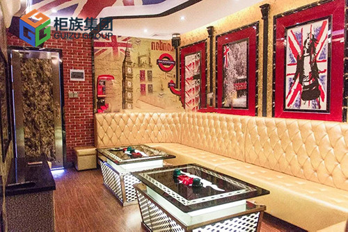
[British style KTV]
The red brick pattern, the rice-shaped flag pattern, and the representative landscape and character pictures all set off a strong natural and elegant British retro atmosphere. The box is equipped with professional audio equipment, large-screen LCD TV and other professional equipment.
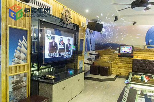
【Ocean Wind KTV】
What do you think of logs, sailboats, sea water, and blue sky? Does closing your eyes feel that you are sailing, and your heart becomes broadened? The singing, the sea, and the voyage are all beautiful sights. Large LCD TVs, professional audio, and song-on-demand facilities are all available.
The Guizu mobile KTV is designed according to high standards. The sound system, WI-FI karaoke device, two front and rear electronic screens, all facilities are available, and the sound absorption and sound insulation are professionally treated with inorganic fiber spraying, sound-absorbing panels and other materials. , Its effect is not inferior to the traditional KTV, and it can be moved quickly and flexibly by a crane. Not limited by venue and construction time. Owning it is equivalent to having an exclusive prop for "opening a private concert".
In metal roofing installation, panel overlap is a crucial step determining the success or failure of the system. This seemingly simple operation is often misunderstood and simplified. Many people fail to realize that proper overlap is the core guarantee of roof waterproofing. Any improper operation, such as insufficient overlap, poor sealing, or misaligned fasteners, can lead to leaks, wind damage, and insulation failure. This guide will explain the key points of proper overlap, helping you ensure the long-term reliability of your roof from the source.
Why Metal Roof Overlap Matters?
Metal roof panels require overlap primarily due to two basic needs:
☆The limited size of individual panels necessitates horizontal and vertical splicing to cover the entire roof;
☆The overlap structure provides a crucial waterproof barrier for the joints.
By stacking the upper panel on top of the lower one, rainwater is guided downwards, preventing it from seeping into the joints, effectively preventing leaks and protecting the building structure. Furthermore, this overlap method enhances the overall wind resistance of the roof and contributes to a neat and aesthetically pleasing appearance.
What are the methods for overlapping steel roofs?
The installation of steel roof panels mainly involves two basic types of overlap: side overlap and end overlap. Side overlaps address the side-by-side connection of roof panels along the width of the roof, while end overlaps address the issue of panel extension along the roof slope. These two methods together constitute the key to roof waterproofing and structural stability.
Side Overlaps:
Ensuring Side-by-Side Connections
End Overlaps:
Extending the Length
Side overlaps refer to the horizontal splicing of panels along the roof. The overlap amount depends on the corrugation or rib profile of the panel. For example, common corrugated panels require at least one overlap at a trough, while box-type panels typically require an overlap at a rib. Under normal conditions, this overlap is sufficient, but in areas with strong winds, the overlap can be increased to enhance overall wind and rain resistance.
When the roof length exceeds that of a single panel, end overlaps are required, where the upper panel is stacked on top of the lower one along the slope. Generally, a minimum overlap length of 150 mm is recommended for roofs with a slope greater than 10°. For gentler roof slopes, this should be extended to 200 mm or more, supplemented with sealing tape or sealant to ensure durable waterproofing of the longitudinal joints.
The overlap length of metal roofing panels needs to be determined based on a combination of factors, including the roof slope, panel profile, and local climate conditions.
Roof Slope
Steeper roofs facilitate drainage, allowing for shorter overlaps. Gently sloped roofs require longer overlaps to prevent water accumulation.
Panel Profile
The depth and design of the panel profile affect drainage efficiency.
Weather Conditions
In areas with strong winds, heavy rain, or blizzards, it is best to increase the overlap length to reinforce the joints.
General practice is as follows: Side overlaps are typically the width of one corrugation or rib; end overlaps are recommended to be at least 150 mm for slopes ≥10°, and should be increased to over 200 mm for gentler slopes or areas with frequent rain and snow. For reliability, the manufacturer's technical specifications should ultimately be followed.
To ensure the strength of metal roofing panel overlaps, the key lies in proper fixing methods, necessary sealing measures, and avoiding common mistakes.
1. Standardized Fixing Procedure
Installation should proceed from the eaves to the ridge, with the panels laid downwind.
Use self-tapping screws with waterproof washers to secure the sheet metal to the purlin below, starting from the crest of the corrugation. Ensure both ends of the overlap are firmly tightened. For large spans or thick sheets, additional fasteners must be installed at the side overlaps according to specifications, or pre-drilled holes to prevent deformation.
2. Use Sealing Materials Properly
In low-slope or high-wind-affected areas, mechanical overlap alone is insufficient to guarantee waterproofing. Butyl sealant tape should be used at the end overlaps, forming an effective seal after the screws are tightened. If using silicone sealants, ensure compatibility with the metal sheet and apply in a continuous, straight line to avoid clogging drainage paths.
3. Avoid Common Installation Mistakes
Avoid insufficient overlap due to material saving and ensure the sheets are stacked correctly (top sheet over bottom sheet). Tighten the screws moderately; overtightening will cause sheet deformation and seal failure. Also, never omit sealing measures in low-slope roofs, and ensure the installation direction follows, rather than opposes, the prevailing wind direction.
The overlapping of steel roof panels is a crucial factor determining the performance and lifespan of the roof. Properly understanding the dimensions and fixing methods for side and end overlaps is essential for achieving lasting waterproofing and structural stability. Whether it's a simple garage or a complex roof, successful installation begins with precise control over this critical detail of overlapping.
If you have any questions,please contact the Yumisteel team for tailored solutions!Thank you!
At first glance, do you think all container houses look exactly the same? This perception often comes from limited exposure to prefabricated structures. In reality, various types exist with distinct features. Today, we will introduce two main categories: flat-pack container houses and expandable container houses.
☆Definition
Flat-pack container houses
Flat-Pack Container Houses are prefabricated structures shipped as disassembled wall panels, roof, and floor sections. These components are bundled for compact transportation, with key frames pre-welded for structural integrity. On-site assembly involves installing the pre-assembled roof and floor frames before attaching wall panels and columns. This method enables efficient logistics—allowing 6-8 units of a 6×2.4m module to fit in a 40-ft container—while ensuring a robust, weathertight building. However, crane or forklift assistance is typically required for positioning the main frames.
Expandable container houses
Expandable folding container houses are prefabricated modular units shipped as complete, fully-formed boxes. Utilizing integrated hinges and folding mechanisms, these structures rapidly deploy on-site by unfolding wall and floor sections to significantly expand interior space. Requiring minimal labor and no complex assembly, they transform from a compact transport configuration into spacious, continuous rooms within hours. This design combines rapid deployment with complete structural integrity, offering an ideal balance of portability and immediate usability.
☆Set up and shipping
Flat-pack houses ship as kits of frames and panels you bolt together.
Flat-pack container houses occupy moderate shipping space—typically 6-8 units fit in a 40-ft container. On-site assembly involves positioning the pre-welded base frame, bolting columns and wall panels, then installing the roof frame. This process generally requires crane or forklift assistance for handling the main structural components.
Expandable houses arrive as a single folded box that unfolds into full rooms in less time.
Expandable container houses ship as near-complete units, typically fitting only 2 modules per 40-ft trailer due to their container-sized folded dimensions. On-site deployment involves unlocking fold-out floors, swinging walls into position, and using integrated jacks or cranes to secure extensions. This design enables remarkably rapid setup despite requiring greater transport space.
☆Roof Performance
Flat-pack houses feature factory-welded roof and floor frames, creating an exceptionally rigid structure. Wall panels are bolted to these frames, often incorporating integrated drainage systems. This welded construction provides superior weather resistance against rain and wind compared to alternative container types.
Expandable houses utilize hinged wall and floor sections with rubber gaskets for sealing. Integrated drainage channels along fold lines direct rainwater away. While highly leak-resistant when properly assembled, their waterproof reliability depends entirely on precise seal installation.
☆ Space & Layout
Flat-pack units offer maximum layout flexibility, functioning as structural shells that allow custom configuration of walls, windows, and partitions. Their standardized dimensions enable seamless side-by-side or vertical stacking to create larger spaces. This system supports tailored room divisions and future expansions, making it ideal for customized residential or commercial applications.
Expandable units feature predetermined layouts defined by their folding mechanisms, typically forming one or two fixed spaces. Delivered with pre-installed interiors including plumbing and electrical systems, they offer immediate usability but minimal reconfiguration potential. This design suits scenarios requiring rapid deployment with standardized, self-contained facilities.
☆Application
Flat-pack Container Houses are ideal for permanent or long-term installations requiring customized layouts and multi-story configurations. Their structural strength and modularity make them perfect for residential complexes, schools, medical clinics, and commercial facilities where spatial flexibility and durability are prioritized.
Expandable Container Houses are optimized for immediate deployment scenarios requiring fully-equipped interiors. These units serve excellently as emergency response shelters, site offices, mobile clinics, and temporary showrooms where rapid setup and operational readiness are critical.
☆Advantages and Disadvantanges
Advantages
Disadvantanges
Flat-Pack Container Houses
Excellent transport efficiency (6-8 units/40ft container); superior structural rigidity with welded frames; outstanding weatherproof performance; flexible modular combinations.
Requires crane equipment for installation; higher initial cost and longer production lead time; relatively complex on-site assembly.
Expandable Container Houses
Rapid deployment (under 1 hour); pre-finished interiors with modern amenities; immediate usability after unfolding.
Fixed internal layout with limited reconfiguration; requires regular maintenance of folding mechanisms; needs substantial clearance for operation; restricted modular connectivity.
Ultimately, your choice between flat packed containers and expandable folding containers hinges on specific project priorities. For maximizing shipping efficiency and storage space, flat packs excel. For projects demanding rapid on-site deployment and minimal labor, expandable containers offer superior convenience, making them ideal for temporary or mobile needs.
If you have any questions,please contact the Yumisteel team for tailored solutions!Thank you!
In industrial construction, the choice between a single-slope roof and a double slope roof is a fundamental decision impacting facility design and performance. These structural forms offer distinct advantages for functionality and cost-efficiency, directly addressing critical factors like climate adaptation, material use, and spatial logistics. This analysis explores the key applications and considerations for single-slope versus double-slope roof systems in modern industrial buildings.
Single-slope Roof
☆Definition
A single-slope roof, also known as a shed roof, is a simple roofing system where the surface slopes in one direction from a higher wall to a lower one. Typically constructed with primary structural members like beams or trusses supporting a cladding deck, it provides efficient drainage, cost-effective construction, and adaptable clear span for industrial or commercial buildings.
☆Advantages
•High Space Utilization
A single-slope roof eliminates dual eaves obstruction, maximizing usable horizontal wall space. This allows for direct installation of large equipment or continuous skylights on the tall gable side, enhancing interior layout flexibility and natural lighting.
•Lower Construction Cost
This design requires only single-side purlins and a simplified drainage system. Compared to a double-slope roof, it reduces structural steel usage by approximately 15%-20%, offering significant material and labor cost savings.
•Clean Aesthetic & Modern Style
Its simple, streamlined form is a hallmark of modern industrial architecture. The single-slope profile is well-suited for technology parks and campuses with strict aesthetic guidelines, providing a visually sleek and contemporary appearance.
☆Disdvantages
•Limited Drainage Efficiency
With only a single drainage slope, this roof design has lower drainage capacity and is prone to water accumulation in heavy rainfall regions, increasing the risk of leaks and water damage over time.
•Potential Need for Wind Reinforcement
The tall gable wall often requires additional structural reinforcement, such as diagonal steel bracing, to prevent deformation under strong winds, especially in typhoon-prone areas like the Philippines.
☆Application
Single-slope roofs are ideal for arid industrial zones like Middle Eastern petrochemical plants, with under 100mm annual rainfall, reducing material use. They suit large-span storage in Texas grain warehouses, enabling wide access doors. Modular designs allow quick expansion in Southeast Asian electronics factories. However, low drainage efficiency limits use in rainy regions, and gable reinforcement is essential in high-wind areas like the Philippines.Single-slope roofs are ideal for arid industrial zones like Middle Eastern petrochemical plants, with under 100mm annual rainfall, reducing material use. They suit large-span storage in Texas grain warehouses, enabling wide access doors. Modular designs allow quick expansion in Southeast Asian electronics factories. However, low drainage efficiency limits use in rainy regions, and gable reinforcement is essential in high-wind areas like the Philippines.
Double Slope Roof
☆Definition
A Double Slope Roof, also known as a gable roof, is a symmetrical roof design formed by two opposing sides pitched at equal angles, typically between 25°-30° for industrial buildings. This classic, stable structure provides efficient dual-direction water drainage, a large internal volume for a clear span, and robust structural integrity for long-term performance.
☆Advantages
•Superior Drainage Efficiency
A Double Slope Roof offers rapid, dual-sided water runoff, channeling rainwater effectively down both slopes. This design provides over 50% greater drainage capacity than a single-slope system in heavy rainfall regions, minimizing the risk of leaks or ponding.
•Enhanced Structural Stability
This symmetrical roof structure features evenly distributed purlins and transmits loads through main steel columns on both sides. The balanced design delivers superior overall stability and improved resistance to wind uplift and seismic forces, especially in active zones.
•Integrated Functionality
The sloped design of a double slope roof allows seamless integration of functional elements. Light strips for natural illumination and roof ventilators for heat dissipation can be installed along the slopes, combining operational efficiency with worker comfort.
☆Disdvantages
•Higher Material and Construction Cost
The double slope roof structure requires more trusses, purlins, and roofing materials compared to a single-slope design, leading to increased initial construction costs and a longer, more complex installation timeline.
•Limitations for Gable-Side Access and Modular Expansion
The symmetrical design restricts the placement of large access openings on the gable ends, which can hinder logistics. It is also less suited for modular, horizontal plant expansion compared to single-slope units that can be easily added side-by-side.
☆Application
Double slope roofis are ideal for demanding industrial applications. Its efficient drainage is crucial in rainy or snowy climates, as seen in European automotive plants. The stable structure supports heavy loads and high insulation standards, like in Japanese precision factories. It also easily integrates sustainable features such as rooftop solar panels for green building certifications.
Single-Slope Roof
Double-Slope Roof
Best for dry climates (low rainfall)
Superior for rainy/snowy climates
Uses less material, lowering cost
Efficient two-sided drainage prevents leaks
Allows large openings on the high side
Creates a symmetrical, stable structure
Easy to expand modularly
Ideal for wide spans and clear interior space
Needs gable wall reinforcement against wind
Generally higher material and construction cost
Ultimately, the choice between a single-slope and double slope roof depends on your specific climate and operational needs. Prioritize a single-slope roof for cost-effective, modular designs in dry regions. Opt for a double slope roof where superior drainage, stability, and integration of sustainable features are paramount.
If you have any questions,please contact the Yumisteel team for tailored solutions!Thank you!
With the fast pace of modern life, foldable houses are becoming an efficient solution for contemporary living. They save time, reduce costs, and are easy to transport. The X-type and Z-type foldable container houses are two popular models. Here, we analyze the differences between these two types of container houses.
The differences between X and Z Folding Container House
☆Definition
X Folding Container House
The X-folding container house is an expandable modular building utilizing a horizontal cross-folding mechanism. It consists of reinforced steel frames, interconnected wall panels, and central locking systems. This prefabricated structure provides rapid deployment, excellent weather resistance, and durable spatial performance. Its compact transport size and quick setup make it ideal for temporary facilities and emergency shelters.
Z Folding Container House
The Z-folding container house is a prefabricated modular structure featuring a unique zig-zag folding wall system. Its core components include reinforced steel frames, interconnected wall panels, and integrated locking mechanisms. This portable building offers excellent structural stability, weather resistance, and rapid deployment capability. The compact folding design ensures maximum space utilization and transportation efficiency, making it an ideal relocatable shelter solution for various temporary applications.
☆Set up and fold method
X Folding Container House
The X-folding container house expands horizontally via a manual pull mechanism. Its four wall assemblies slide outward along tracks, doubling the floor space. After unfolding, locking pins are secured for stability, enabling rapid deployment without heavy machinery.
Z Folding Container House
The Z-folding container house features a zig-zag folding mechanism. It expands from a compact unit by lifting the roof, which unfolds walls automatically. Locking pins secure the structure, enabling rapid, crane-free setup and repeated use.
☆Roof Performance
X Folding Container House
The X-type utilizes a simpler roof formed by folded wall panels, relying primarily on sealants for waterproofing. While functional in mild conditions, it requires regular maintenance of fold-line seals and demonstrates limited performance in extreme weather situations compared to reinforced designs.
Z Folding Container House
The Z-type features a reinforced roof structure with integrated gaskets and drainage systems, providing exceptional load-bearing capacity and waterproofing. It effectively handles heavy rain and snow, preventing water pooling and leakage for reliable all-weather protection with minimal maintenance requirements.
☆Space & Layout
X Folding Container House
The X-type features an open-plan layout with minimal internal divisions, creating flexible single-space interiors. This configuration is particularly suitable for temporary pop-up offices and short-stay housing where rapid deployment and open spaces are prioritized over room separation.
Z Folding Container House
The Z-type design creates defined room divisions, offering clear separate spaces ideal for two-bedroom configurations. This layout provides enhanced privacy and organization, making it well-suited for staff housing, rental units, and other applications requiring structured long-term living arrangements.
☆ Application
X Folding Container House
The X-type model suits temporary projects where cost-effectiveness and simplicity are prioritized. Designed for under 50 folding cycles and a 5-8 year lifespan, it serves well for pop-up offices, short-term housing, and event spaces where minimal relocation and basic functionality are required.
Z Folding Container House
The Z-type model is engineered for projects requiring frequent relocation and long-term use, supporting over 100 folding cycles and offering a 15-year service life. Its durable construction and enhanced weather resistance make it ideal for permanent installations, repeated deployments, and applications demanding high durability.
In summary, the choice between X and Z folding container houses depends on your specific project requirements. The Z-type folding house offers superior durability, long-term performance, and excellent weather resistance, making it ideal for frequent relocation and extended service life. Conversely, the X-type folding container house provides cost-effective simplicity perfect for temporary installations and short-term needs. Carefully evaluating your timeline, mobility requirements, and environmental conditions will ensure you select the most suitable prefabricated housing solution. Both modular designs deliver practical portable architecture while serving distinct application scenarios.
If you have any questions,please contact the Yumisteel team for tailored solutions!Thank you!
In today's rapidly developing industrialized construction and large-scale infrastructure projects, the application of heavy precast components (such as prestressed double-T slabs, ultra-large span beams, giant wall panels, and nuclear power modules) has become commonplace. They have brought a leap in construction efficiency and a high degree of control over project quality. However, every movement of these behemoths—especially during hoisting—affects the safety of the entire project.
The hoisting anchoring system is the most critical link in this safety chain. Improper selection can lead to component damage and project delays, or even catastrophic accidents. So, faced with a dazzling array of anchoring products on the market and complex working conditions, how can we make a scientific, safe, and economical choice?
Before making a selection, we must be the ones who know the component best. Key information includes:
1. Component weight and center of gravity: This is the most crucial data. Not only must the total weight be known, but the location of the center of gravity must also be clearly defined through the design drawings to ensure balanced stress during hoisting and prevent overturning.
2. Concrete strength: The load-bearing capacity of the anchoring system is directly related to the strength of the concrete. The early strength (release strength) and design strength of the component at the time of hoisting must be clearly defined.
3. Component size and shape: Is it a slender beam, a wide slab, or an irregularly shaped component? This determines the possibilities and number of hoisting points.
4. Reinforcement distribution: The anchors must coexist harmoniously with the internal reinforcement mesh of the component to avoid conflict. Detailed reinforcement layout drawings are essential.
Common hoisting and anchoring methods include the following:
Embedded parts are one of the commonly used anchoring methods in the hoisting of precast components. The material properties and construction calculations of embedded parts should comply with the provisions of current national standards. During the production of precast components, anchors should be accurately embedded according to design requirements to ensure that their position and quantity meet the hoisting needs. The bearing capacity of embedded parts needs to be strictly calculated to meet the stress requirements under various working conditions during hoisting. For example, when tower cranes, temporary supports, and other equipment are attached to precast components, embedded parts must be set according to stress calculations.
(II) Anchoring with Through-Wall Bolts
For some precast wall components, through-wall bolts can be used for anchoring. During the production of precast components, through-wall holes should be reserved, and relevant reinforcement measures should be designed at this location. The hole diameter and position of the through-wall bolts should be strictly set according to design requirements to ensure the reliability of the anchoring.
(III) Anchoring with Embedded Nuts or Bolts
Embedded nuts or bolts are another commonly used anchoring method. The advantages of this method are convenient lifting and the ability to select the appropriate method based on the corresponding product standards. During the prefabrication of components, embedded nuts or bolts are pre-embedded inside the components, ensuring accurate positioning. During lifting, a special lifting tool connected to the lifting equipment works in conjunction with the embedded nuts or bolts to achieve stable lifting of the components.
Matching component information with anchorage type requires a systematic evaluation of the following five points:
1. Bearing Capacity and Safety Factor
* Absolute Red Line: The rated working load of the anchorage system must be greater than the weight of the component it supports.
* Dynamic Effects: The dynamic factor during lifting (typically 1.5 to 2.5, or even higher) must be considered in calculating the design load.
* Safety Factor: Select certified products with a high safety factor (typically ≥4:1 or 5:1). Never use substandard or counterfeit products.
2. Failure Mode – Concrete is Key
An excellent anchorage system is designed so that the yielding of the steel (lifting rod or anchorage) precedes the failure of the concrete. This means that in the event of overload, you will see a "warning" of steel deformation and elongation, rather than the brittle failure of sudden concrete collapse. Therefore, concrete cone failure calculations must be performed.
3. Number and Layout of Lifting Points
* Basic Principle: Ensure smooth lifting of the component and uniform stress distribution at each lifting point.
* Quantity: Depending on the weight and shape of the component, typically 2, 4, or more lifting points are required.
* Arrangement:The line connecting the lifting points should pass through the component's center of gravity, and the angle between the line and the horizontal plane (sling angle) should generally not be less than 60°. The smaller the angle, the greater the stress on the lifting point.
4. Ease of Installation and Repeatability:
* Disposable vs. Reusable: Embedded anchors are usually disposable, while some specialized lifting tools are reusable, requiring a cost-benefit analysis.
* Installation Speed:In large projects, rapid anchoring significantly improves efficiency.
5. Long-Term Impact on Components:
* Exposed: Embedded internal threaded sleeves can be capped after lifting, having no impact on the building's aesthetics. Exposed anchors may require later cutting, increasing procedures and costs.
* Impact on Structural Performance: Embedded anchors should not weaken critical sections of the component or interfere with prestressing tendons.
Selecting a hoisting and anchoring system for heavy precast components is not a simple matter of "whichever looks best," but a rigorous and systematic engineering decision-making process. It requires us to start with the characteristics of the components, deeply understand the principles of various anchoring methods, and make a comprehensive judgment based on the principles of safety, economy, and efficiency.
Remember, the hoisting and anchoring system is the lifeline connecting the "stationary" and the "moving." Investing extra effort in it is adding the strongest insurance to the smooth progress of the entire project and the safety of everyone involved.
In the precast concrete manufacturing process, the method of fixing the formwork is one of the key factors affecting production efficiency, cost, and product quality. With the development of technology, magnetic systems have gradually become an emerging method of formwork fixing, bringing about many significant changes compared to traditional formwork clamps.
01 Fundamental Differences in Technical Principles
The application of magnetic systems and traditional formwork clamps in precast plants is primarily reflected in their fundamentally different working principles.
Traditional formwork clamps typically rely on mechanical fastening, such as screws, bolts, and clamps, applying physical pressure to the mold to achieve fixation. This method requires pre-drilling or welding into the formwork and platform, with each connection point requiring individual fasteners and manual operation.
Magnetic systems, on the other hand, rely on the strong attractive force of permanent magnets. The magnetic field generated by high-performance neodymium magnets firmly bonds the formwork to the steel platform.
The working principle of magnetic systems is not complex. These devices contain high-performance permanent magnets. A magnetic control box enhances and shields the magnetic force of the internal magnetic blocks, keeping them in an active or inactive state. When the magnetic box is active, the holding surface at the bottom of the magnetic block adheres tightly to the precast concrete production platform, providing a secure hold.
When the magnetic block is pried up with a lever, most of the magnetic force is shielded by the magnetic control box, significantly reducing the bottom magnetic force, allowing the magnetic box to be easily removed from the platform manually. This technology avoids dependence on external energy sources and works entirely based on the physical properties of the magnets themselves.
02 Comparative Analysis of Efficiency and Cost
In precast component production, time is money. The difference in efficiency and cost between magnetic systems and traditional clamps directly determines the project's profitability.
Traditional clamps require drilling, installing screws, and tightening bolts one by one. This process is not only time-consuming but also prone to errors. Taking stair precast component molds as an example, traditional side mold connections require top screw fixing and bottom pin positioning, making the operation complex.
Magnetic systems significantly improve installation speed. Industry data shows that using magnetic systems can reduce template installation time by more than 70%. A simple magnetic box switch can instantly and firmly fix the entire side mold, eliminating the need to adjust each fastener individually.
From a cost perspective, while traditional template clamps have a lower initial investment, their long-term operating costs are higher. Mechanical fasteners are easily damaged and require regular replacement; drilling and welding can cause permanent damage to the mold platform, shortening its lifespan; and labor costs remain consistently high.
In contrast, while magnetic systems have a higher initial investment, they offer significant cost advantages. Once installed, the magnetic device can be reused thousands of times, far exceeding the lifespan of traditional clamps. Since no drilling or welding is required, the formwork and mold table remain intact, significantly reducing maintenance costs.
The precast concrete magnet can withstand a weight of 2100 kg, making it extremely lightweight and suitable for use in precast concrete plants. It can be easily accessed by crane. This strong load-bearing capacity enables it to meet the production needs of the vast majority of precast components.
03 Key Performance Data Comparison
The table below illustrates the performance differences between the magnetic system and traditional template clamps from multiple perspectives:
Comparison Dimensions
Magnetic system
Traditional template clamps
Installation speed
Approximately 30% of the time of traditional methods
Baseline time
Disassembly speed
Approximately 20% of the time of traditional methods
Baseline time
Number of times it can be reused
Thousands of times
Hundreds of times
Damage to the mold table
No damage
Drilling and welding are required, causing permanent damage.
Single connection point load-bearing capacity
600-2100 kg
Limited by fastener strength
Labor intensity
Low cost, requires minimal physical labor
The work is demanding, requiring tasks such as tightening screws and drilling.
Adaptability
Adapt to multiple templates via adapter
Custom fixtures are required.
Temperature adaptability
Operating environment up to 80°C
Limited by the thermal expansion of materials
The data shows that magnetic systems have significant advantages in terms of efficiency, durability, and adaptability, especially in assembly line production environments where frequent disassembly and assembly of templates are required.
04 Enhanced Quality and Precision
The quality of precast components directly impacts the safety and durability of buildings. In this regard, the magnetic system demonstrates its unique advantages.
Traditional clamps, relying on manual tightening, are prone to inconsistent tightening force, leading to formwork deformation or displacement, which in turn affects the dimensional accuracy of concrete components. This is especially true during vibration table operations, where traditional clamps are prone to loosening and formwork displacement.
The magnetic system, however, provides continuous and uniform clamping force through evenly distributed magnetic points. For example, the LSC-2100 magnetic box has a vertical pull-out force exceeding 2100 kg, and its uniform attraction ensures that the formwork does not shift during production.
The magnetic system also significantly improves the formwork's reset accuracy. Since re-alignment is unnecessary, the formwork can be accurately reset after each assembly and disassembly, greatly improving the dimensional consistency of components during mass production. This is crucial for prefabricated buildings, as the dimensional accuracy of components directly determines the efficiency of on-site installation and the overall quality of the building.
05 Application Scenarios and System Types
Magnetic systems are widely used in precast plants, covering various component production scenarios from simple to complex.
The most basic application is side mold fixing. The side mold is firmly attached to the mold table using magnetic boxes; this is the most common application. Depending on whether the mold table is fixed or vibrating, and the height of the mold (component thickness), different magnetic boxes with varying suction power and sizes can be selected.
For example, when producing composite slabs on a fixed mold table, a magnetic box with a suction power of 600-1000 kg is selected, while a magnetic box with a suction power of 1000 kg is required when producing composite slabs on a vibrating mold table. When producing wall panels, magnetic boxes with a suction power of 1350 kg or 1800 kg are needed.
Magnetic side molds offer a more integrated solution. This type of mold embeds the magnetic suction cup system directly into the steel mold, forming an integrated design. Because the suction cup system is located inside the steel mold groove, concrete residue or other contaminants will not damage the entire mold system.
Embedded component fixing magnetic bases are another important application. When producing precast concrete components, various switch holes and pipe holes need to be left, and various connection or lifting sleeves also need to be pre-embedded. Magnetic bases are used for fixing, which does not damage the platform, ensures the embedded parts do not slip, and guarantees a secure fixation.
In addition, there are specialized tools such as magnetic chamfering strips used to create neat chamfers on the edges of precast concrete components. These rubber magnetic chamfering strips are lighter than iron chamfering strips and also have a certain degree of flexibility, greatly facilitating their use in actual production.
06. Dual Considerations for Safety and Environment
Safety is always paramount in the construction industry. Magnetic systems offer significant improvements in this regard.
Traditional formwork clamps require the use of power tools and welding, posing a high risk of worker injury. Magnetic systems drastically reduce these risks—eliminating the need for drilling and welding, reducing the use of heavy tools, and eliminating sparks and flying metal debris during operation.
Especially in assembly line operations requiring frequent formwork adjustments, traditional methods may require overhead cranes for installation and dismantling, while magnetic systems allow for most tasks to be completed manually, reducing the safety hazards associated with large equipment.
From an environmental perspective, magnetic systems are also more advantageous. Traditional clamps generate significant amounts of metal debris and exhaust fumes during use, while magnetic systems produce virtually no pollutants.
Furthermore, the ability to be reused thousands of times greatly reduces material consumption and waste generation. The reusable nature of magnetic systems makes them a more sustainable construction technology option.
Frequently Asked Questions
Q: How strong is the attraction force of a precast magnetic system?
A: Precast magnetic systems provide reliable attraction force, typically ranging from 500 kg to over 1800 kg per unit, depending on size and design. They are carefully designed to withstand the pressure of new concrete and ensure precise alignment of the formwork.
Q: Is it safe to use a magnetic formwork system near steel molds?
A: Yes! These systems are specifically designed for steel molds. The magnets provide a strong holding force without damaging the mold, and their design ensures a uniform distribution of attraction force, preventing deformation.
Q: Can I add magnets to my existing formwork system?
A: Absolutely. Many magnetic systems are compatible with existing molds. Retrofitting usually requires only minor adjustments and can significantly improve efficiency without replacing major equipment.
Q: What are the maintenance requirements for precast magnets?
A: Magnetic systems have low maintenance costs. Regular cleaning to remove concrete residue and occasional checks for surface wear or corrosion ensure long-term performance and safety.
Q: Are magnetic formwork systems suitable for all types of concrete?
A: Magnetic formwork is suitable for most concrete mixtures, including high-strength concrete, lightweight concrete, and precast concrete. However, for concrete mixtures with very coarse particles or high fiber content, careful placement may be necessary to ensure uniform contact and secure fixation.
In modern industrial fields, from aerospace to medical devices, from desalination to chemical processing, titanium tubes have become the material of choice in many critical applications due to their superior performance. However, when you need to purchase titanium tubes, you face a fundamental choice: seamless titanium tubes or welded titanium tubes? Understanding the differences and advantages of each is crucial to ensuring project success.
Seamless titanium tubes are made by heating a solid titanium billet, then perforating it with a piercing machine, and finally processing it through rolling or drawing. The entire process does not involve any welding, so the pipe is structurally completely continuous.
Heating and Perforation: Heating the titanium billet to the appropriate temperature and then perforating it
Rolling and Forming: Forming the tube through a rolling process
Finishing: Achieving the final size and performance through processes such as cold drawing and heat treatment
Unique Advantages of Seamless Titanium Tubes
1. Excellent Structural Integrity
Seamless titanium tubes have no welds, which means the entire pipe cross-section has uniform mechanical properties, without the weak points that welding might introduce. This characteristic makes them more reliable under high pressure, high temperature, or extreme operating conditions.
2. Superior Corrosion Resistance
Because there are no welds, seamless titanium tubes avoid microstructural changes and potential corrosion problems that may occur in welded areas. This is especially important for applications involving corrosive chemicals or seawater.
3. Higher Pressure Resistance
The seamless structure allows titanium tubes to withstand higher internal and external pressures, making them ideal for high-pressure systems (such as aerospace hydraulic systems and high-pressure heat exchangers).
4. Excellent Surface Quality
Seamless titanium tubes typically have smoother inner and outer surfaces, reducing flow resistance and preventing the accumulation of deposits. This makes them particularly suitable for applications requiring high levels of cleanliness, such as medical equipment or food processing.
5. Wide Range of Size Adaptability
Although manufacturing large-diameter seamless titanium tubes is more difficult, for small and medium-diameter pipes, the seamless process provides more precise wall thickness control and dimensional consistency.
Comparison of Seamless Titanium Tubes and Welded Titanium Tubes
Feature Comparison
Seamless Titanium Tube
Welded Titanium Tube
Welded Titanium Tube
Formed in one piece through piercing and rolling
Made by rolling and welding titanium plates/strips
Structural Continuity
Completely continuous, no welds
Has longitudinal or spiral welds
Wall Thickness Uniformity
Excellent, precisely controllable
Good, but slight variations may occur in the weld area
Pressure Resistance
Higher, evenly distributed
Good, but the weld may be a weak point under pressure
Corrosion Resistance
Uniform throughout, no weld-affected zone
Good, but the weld area may have slight differences
Cost Factors
Higher, especially for large diameter pipes
Relatively lower, especially suitable for large diameter thin-walled pipes
Size Range
Significant advantages for small and medium diameters
More suitable for large diameter, thin-walled pipes
Production Cycle
Relatively longer
Usually shorter, especially for standard sizes
Welded titanium tubes are also an excellent choice in many applications:
Cost-effective: For large-diameter or thin-walled pipes, welded titanium tubes are often more cost-effective.
Size flexibility: Extra-large diameter titanium tubes can be produced.
Fast delivery: Standard sizes of welded titanium tubes usually have shorter delivery times.
Technological advancements: Modern welding technologies (such as TIG and plasma welding) can produce high-quality welds.
How to choose: Application scenario guide
Situations for choosing seamless titanium tubes:
High-pressure systems (working pressure exceeding the capacity of welded pipes)
Extreme corrosive environments (especially to avoid the risk of weld corrosion)
Applications requiring extremely high fatigue life
Situations for choosing welded titanium tubes:
Large-diameter low-pressure pipelines
Cost-sensitive projects with non-extreme operating conditions
Non-pressure-bearing components such as heat exchanger shells
Standard size pipes requiring fast delivery
Large structural components
Both seamless and welded titanium tubes have their advantages and applicable scenarios. Seamless titanium tubes are irreplaceable in the most demanding applications due to their superior structural integrity, corrosion resistance, and pressure bearing capacity. Welded titanium tubes, on the other hand, provide a practical solution in cost-sensitive or large-size applications. NBSM provides high-quality seamless titanium tubes and can provide a full range of certification documents.