In the competitive landscape of telecommunication and power transmission infrastructure, the upfront engineering design of an angle steel tower is often celebrated for its structural elegance and load-bearing efficiency. However, the true determinant of project profitability and timeline success lies not only in what is designed but in how it is built. A design that looks perfect on paper can harbor prohibitive hidden costs in fabrication, logistics, and field assembly. This is where Design for Manufacturing and Installation (DFMI)—a proactive, holistic engineering philosophy—becomes the critical lever for cutting total project cost and mitigating risk.


angle steel tower


DFMI moves beyond pure structural calculation to integrate the constraints and opportunities of the entaily chain: shop fabrication, transportation, and field erection. Its core principle is simple: optimize the design for the entire lifecycle from workshop to commissioning, thereby eliminating waste, reducing complexity, and accelerating deployment.


The Hidden Cost Killers in Traditional Tower Projects

Before applying DFMI, it's crucial to identify where costs and delays typically hide:

  1. Fabrication Complexity: Excessive unique part numbers, non-standard connection details, and intricate welding requirements drive up shop labor hours, increase material handling, and elevate the risk of error.

  2. Logistical Inefficiency: Components designed without regard to standard trucking dimensions, weight limits, or container sizes lead to costly oversized shipments, complex securing schemes, and multiple trips.

  3. Installation Bottlenecks: Designs that are difficult to sequence, align, or bolt together on-site—especially under challenging weather or in remote locations—result in prolonged crane rentals, higher labor costs, and significant schedule overruns.

DFMI systematically attacks these areas through three pillars: Standardization, Modularization, and Installation-Centric Detailing.


angle steel tower


Pillar 1: Standardization for Fabrication Efficiency

The goal is to reduce variation and simplify the bill of materials (BOM).

  • Standardized Connection Nodes: Instead of customizing each bolted joint, DFMI employs a library of pre-engineered, pre-calculated connection types (e.g., standard gusset plate details for specific force ranges). This allows for:

    1. Batch production of identical components.

    2. Use of jigs and fixtures for faster, more accurate assembly.

    3. Reduced engineering and drafting time for repetitive elements.

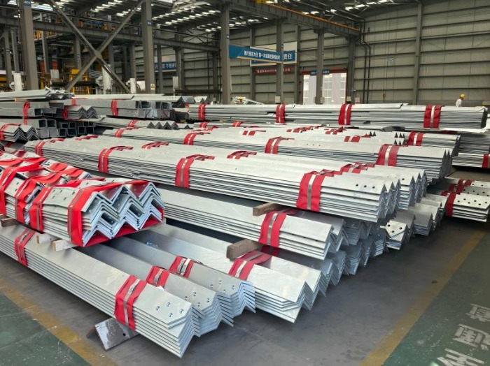
  • Minimized Part Proliferation: By rationalizing member lengths and cross-sections, the number of unique part codes can be drastically reduced. This simplifies procurement, inventory management, and quality control in the factory.

  • Design for Automated Processes: Details are tailored for efficient CNC punching/drilling and hot-dip galvanizing. This includes ensuring adequate hole clearances for galvanizing drainage, avoiding trapped air pockets, and designing for easy dipping and handling.


Pillar 2: Modularization for Optimal Transport and Handling

Here, design is governed by the logistics corridor from factory to site.

  1. Transportation Geometry: The maximum dimensions and weight of any shipping module are dictated by standard flatbed trailer or container specifications. DFMI breaks down the tower into the largest possible modules that still comply with these limits, minimizing the number of shipments and crane lifts.

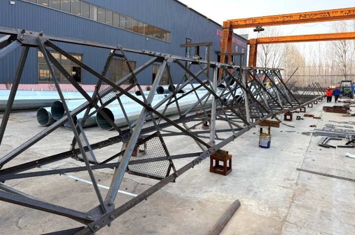
  2. Pre-Assembled Submodules: Where possible, smaller components are permanently joined in the controlled factory environment to form larger, rigid submodules (e.g., complete bracing panels, leg sections with pre-attached ladders). This shifts labor from the challenging field environment to the efficient shop floor, drastically cutting on-site assembly time.

  3. Integrated Lifting and Rigging Points: Lifting lugs or pick points are designed into major modules. Their location is calculated to ensure balanced, stable lifts, and they are fabricated as an integral part of the component, eliminating the need for unsafe and time-consuming field-attached slings.


angle steel tower


Pillar 3: Installation-Optimized Detailing

The design actively enables fast, safe, and error-proof field assembly.

  1. Bolted Connections Over Welding: While not always possible, prioritizing bolted connections for major field splices is a cornerstone of DFMI. This requires precision in hole alignment, achieved through match-marking and the use of drill jigs during fabrication. It eliminates the need for highly skilled field welders, expensive welding equipment, and time-consuming non-destructive testing (NDT) on-site.

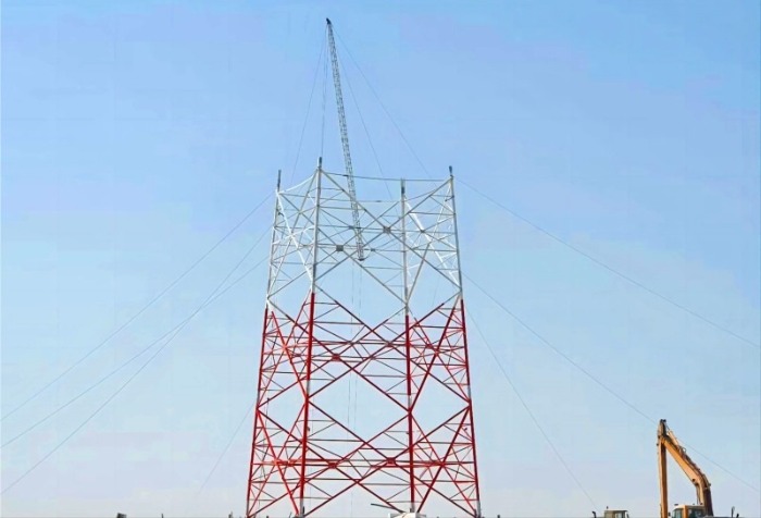
  2. Self-Guiding and Self-Supporting Features: Components are detailed to fit together in only one correct way. This can include tapered spigots for leg alignment, unique bolt patterns to prevent incorrect assembly, and temporary connection points for torsional bracing during the erection sequence.

  3. Sequential Erection Clarity: The DFMI process produces clear assembly sequence drawings that guide the erection crew. The design itself facilitates this sequence, ensuring stability at every intermediate stage without requiring excessive temporary supports.


The Tangible ROI of DFMI

Implementing a rigorous DFMI approach yields measurable benefits across the project lifecycle:

  1. Reduced Fabrication Cost: Lower labor hours, less material waste, and higher workshop throughput.

  2. Predictable Logistics: Fewer shipments, lower freight costs, and simplified customs documentation for international projects.

  3. Accelerated Installation: Site work can be reduced by 30-50%, minimizing weather exposure and rental costs for heavy equipment.

  4. Enhanced Quality & Safety: Controlled factory production ensures higher, more consistent quality. Ergonomic and safer installation sequences reduce on-site risks.

  5. Lower Total Cost of Ownership (TCO): While DFMI may require slightly more upfront engineering investment, the savings across fabrication, logistics, and installation overwhelmingly deliver a superior project ROI.


angle steel tower


Conclusion: Engineering for the Real World

For angle steel tower projects, DFMI is not a luxury but a necessity for remaining competitive and profitable. It represents a shift in mindset—from the engineer as a pure analyst to the engineer as an integrator of the entire value chain. By designing with the fabricator's workshop, the truck driver's route, and the erection crew's wrench in mind, we move beyond creating merely adequate structures to delivering optimized assets where efficiency, cost, and reliability are engineered in from the very first sketch. In an industry where margins are tight and schedules tighter, DFMI is the definitive strategy for cutting the hidden costs that traditional design leaves on the table.


 Learn more at   www.alttower.com

Contact Us

In the demanding world of telecommunications infrastructure, where the failure of a single tower can disrupt networks for millions, the choice of support structure is a critical engineering decision. When the application involves heavy loads—such as massive 5G MIMO antennas, large parabolic microwave dishes, or the combined equipment of multiple network operators—standard designs often reach their limit. For these mission-critical, high-capacity scenarios, the 4-legged angle steel tower stands apart, offering a level of stability and load-bearing capacity that is truly unbeatable. This superiority is not accidental; it is the direct result of fundamental structural mechanics and deliberate design optimization.


angle steel tower


The Geometry of Strength: A Foundation of Inherent Stability

The core advantage of the 4-legged, or quad-legged, design lies in its geometry. This configuration creates a structure with exceptional torsional rigidity and a highly efficient load path.

  1. · Superior Moment Resistance: The wide, rectangular or square base formed by the four legs provides an enormous lever arm to resist overturning moments caused by high winds or asymmetric antenna loading. This is quantified in engineering as a high "polar moment of inertia."

  2. · Optimal Load Distribution: Vertical loads from equipment weight and ice accumulation are channeled directly down the four primary legs. More importantly, lateral forces from wind are transformed into predictable axial loads (tension in one leg, compression in the opposite) within the tower's robust bracing system. This efficient distribution prevents localized stress concentrations that can lead to fatigue or failure.

  3. · Redundant Load Paths: Unlike a monopole, which is a single, critical element, the 4-legged lattice design is a highly redundant system. The network of horizontal and diagonal bracing members between legs creates multiple pathways for forces to travel, ensuring structural integrity even in the unlikely event of a minor component issue.


angle steel tower


Engineered for Extreme Environmental Loads

Heavy-load applications are defined not just by the weight of the equipment but by the severe environmental forces the tower must withstand. The 4-legged design is uniquely suited for this challenge.

  1. · Conquering Wind Loads:
    High winds are the dominant dynamic force on any tall structure. For a tower laden with large, sail-like antennas, this force is magnified. The 4-legged lattice tower combats this through aerodynamics and strength. Its open-frame design allows wind to partially pass through, significantly reducing the overall wind pressure coefficient compared to a solid-sided monopole of equivalent capacity. The triangulated bracing system then effectively transfers these reduced but substantial forces down to the massive foundation, minimizing sway and preventing the destructive dynamic vibrations that can affect radar or microwave signal precision.

  2. · Supporting Massive Ice Loads:
    In cold climates, radial ice accumulation on antennas, cables, and the tower itself can add tons of extra weight. The 4-legged tower's design inherently accommodates this. Its formidable structural capacity is calculated with significant ice-loading scenarios in mind (as per standards like TIA-222 or EN 1993-3-1). The tower's ability to handle this immense additional dead load, combined with the increased wind drag from iced profiles, is a key factor in its selection for harsh environments.


self support tower


The Ideal Host for Multi-Operator and High-Capacity Sites

The modern telecommunication landscape is defined by shared infrastructure and dense equipment arrays. This is where the 4-legged tower transitions from a strong option to the only viable one.

  1. · Unmatched Platform Real Estate: The four-cornered structure provides abundant space for mounting platforms at multiple elevations. This allows for the clear vertical and horizontal separation of antennas from different operators (a practice known as "sectorization"), which is crucial to prevent radio frequency interference. A single 4-legged tower can comfortably host the complete suite of 2G, 3G, 4G, and 5G equipment for three or more carriers, alongside multiple microwave backhaul links.

  2. · Heavy Antenna Support: Next-generation equipment, such as 5G Massive MIMO antenna arrays and full-band radios, are notably heavier and bulkier than their predecessors. The robust structural nodes and connection points of a 4-legged tower are designed to handle these concentrated loads safely, without the deflection or creep that could misalign sensitive microwave signals over time.

  3. · Future-Proofing and Expansion: The lattice framework is inherently modular. Adding new platforms, extending height, or reinforcing specific sections to carry next-generation equipment is a straightforward engineering task. This scalability protects the long-term investment in the site.


self supporting towers


Conclusion: The Benchmark for Mission-Critical Infrastructure

When the requirement is for absolute reliability under the heaviest equipment loads and most severe environmental conditions, the decision is clear. The 4-legged angle steel tower delivers unbeatable stability through its optimal geometric efficiency, superior load distribution, and immense structural redundancy. It is the engineering benchmark for hosting multi-operator networks, large-scale microwave hubs, and future technologies, ensuring that vital communication links remain operational for decades. In the world of heavy-load applications, it is not merely a choice but the definitive solution for stability and longevity.

As telecommunications networks evolve to support 5G and future generations of wireless technology, the demand for taller towers continues to grow. While conventional towers typically max out around 80 meters, next-generation networks require structures that can reach 100 meters and beyond. Enter the 4-legged angle steel tower – an engineering solution specifically designed to break through conventional height limitations while maintaining structural integrity and operational reliability.


self support tower


The Height Challenge: Why Conventional Designs Fail

Traditional tower designs face significant challenges when exceeding 80 meters:

  1. -Exponential increase in bending moments from wind loads

  2. -Buckling risks in compression members

  3. -Dynamic wind effects causing complex vibration patterns

  4. -Foundation stability concerns under combined loading conditions

The transition from 80 to 100+ meters represents more than just adding height – it requires a fundamental rethinking of structural principles and load management strategies.


4 legged self support tower


Four-Legged Configuration: The Structural Advantage

The quadrilateral geometry of 4-legged towers provides distinct advantages for extreme-height applications:

Enhanced Stability Mechanism

  1. -Wider base dimensions create significantly larger resisting moments

  2. -Redundant load paths distribute stresses more efficiently than three-legged designs

  3. -Superior torsional rigidity prevents twisting under asymmetric loading

  4. -Progressive failure prevention through multiple redundant members

Material Efficiency

  1. -Optimized bracing patterns maximize strength-to-weight ratios

  2. -Segmented construction allows for varying cross-sections along the height

  3. -Strategic member sizing places heavier sections where stress concentrations occur


Critical Technical Considerations for 100+ Meter Towers

Advanced Buckling Analysis
Traditional Euler buckling calculations prove insufficient for ultra-tall towers. Our engineering approach incorporates:

  1. -Non-linear finite element analysis to predict complex buckling modes

  2. -Initial imperfection sensitivity studies accounting for fabrication tolerances

  3. -Local-global interaction buckling assessment for compression members

  4. -Dynamic buckling evaluation under wind-induced vibrations

Wind Engineering Innovations
At heights exceeding 80 meters, wind behavior becomes increasingly complex:

  1. -Aeroelastic effects requiring specialized damping systems

  2. -Wind speed gradient modeling across the tower height

  3. -Vortex shedding mitigation through helical strakes or tuned mass dampers

  4. -Directional wind analysis for site-specific loading conditions

Non-Linear Dynamic Response
Our design methodology addresses several critical dynamic phenomena:

  1. -Galloping instability prevention through member shape optimization

  2. -Wake-induced vibrations in multi-tower configurations

  3. -Rain-wind induced vibrations and their mitigation

  4. -Seismic-wind combination effects for regions with multiple hazards


120m angle steel tower


Foundation Engineering for Extreme Heights

The foundation system for 100+ meter towers represents one of the most critical design elements:

Soil-Structure Interaction

  1. -Deep foundation solutions using large-diameter bored piles

  2. -Pile group efficiency optimization for lateral load resistance

  3. -Soil-structure interaction modeling to accurately predict deformations

  4. -Uplift resistance mechanisms using underreamed piles or rock anchors

Advanced Foundation Types

  1. -Raft foundations with integrated pile systems for difficult soil conditions

  2. -Rock-socketed foundations in mountainous terrain

  3. -Slab-base designs with ground improvement techniques

  4. -Multi-level foundation systems for sloped sites


Case Study: 118-Meter Tower Project

A recent project demonstrates our approach to extreme-height tower design:

Project Specifications

  1. Height: 118 meters

  2. Location: Coastal region with high wind speeds

  3. Loading: Multiple carrier antennas + microwave links

  4. Design life: 50 years

Technical Solutions Implemented

  1. -Hybrid bracing system combining K-bracing and X-bracing patterns

  2. -Tuned mass damper at 95-meter level for vibration control

  3. -Rock-anchored foundation with 32-meter deep piles

  4. -Progressive member sizing with heavier angles at lower sections

Performance Results

  1. -Natural frequency: 0.45 Hz, well separated from vortex shedding frequencies

  2. -Peak acceleration: <15 mg under 50-year wind conditions

  3. -Foundation settlement: <12 mm after 2 years of monitoring


self supporting towers


Material and Fabrication Innovations

High-Strength Steel Applications

  1. -Q420 steel (yield strength 420 MPa) for critical compression members
  2. -Hybrid construction using varying steel grades based on stress requirements
  3. -Cold-formed angles with enhanced buckling resistance

Advanced Connection Design

  1. -High-strength bolting with pre-tensioned connections

  2. -Moment-resistant joints at key structural intersections

  3. -Slip-critical connections for fatigue-sensitive locations


Monitoring and Maintenance Considerations

Ultra-tall towers require specialized monitoring systems:

  1. -Structural health monitoring with strain gauges and accelerometers

  2. -Foundation settlement monitoring using precision instruments

  3. -Corrosion protection systems with enhanced coating specifications

  4. -Robotic inspection systems for difficult-to-access areas


Future Directions: Beyond 150 Meters

The engineering frontier continues to advance with several emerging technologies:

  1. -Composite materials combining steel with carbon fiber elements

  2. -Active damping systems using real-time response control

  3. -Digital twin technology for predictive maintenance

  4. -Adaptive structures that modify their properties in response to loading


Conclusion: Engineering Without Height Limits

The 4-legged angle steel tower design represents a proven solution for pushing beyond the conventional 80-meter barrier. Through advanced buckling analysis, sophisticated wind engineering, and innovative foundation design, these structures can safely reach 100+ meters while maintaining operational reliability.

As network demands continue to evolve, the ability to build higher will remain crucial for providing comprehensive coverage and capacity. The 4-legged configuration, with its inherent stability and redundant load paths, provides the engineering foundation for these next-generation towers.

At Qingdao Altai Tower, we're committed to advancing tower technology through rigorous engineering and innovative design. Our experience with extreme-height projects demonstrates that with the right approach, there are no inherent limits to how high we can build – only new engineering challenges to solve.


 Learn more at  www.alttower.com


Contact Us

As telecommunication providers race to expand network coverage—whether for 4G, 5G, or future technologies—the choice of infrastructure plays a critical role in determining the speed, cost, and long-term viability of large-scale rollouts. Among the available options, 3-legged lattice towers stand out as a proven, cost-effective solution for bridging vast urban and rural areas. This blog explores the structural, logistical, and economic factors that make these towers ideal for massive network deployments.


three legged tower


1. The Challenge of Large-Scale Network Rollouts

Deploying thousands of towers across diverse terrains requires balancing three key constraints:

  1. Capital Expenditure (CAPEX): High upfront costs for materials, transportation, and installation.

  2. Operational Expenditure (OPEX): Ongoing maintenance, energy consumption, and site management.

  3. Scalability: The ability to rapidly scale infrastructure without compromising reliability.


Traditional monopoles or tubular structures often struggle to meet these demands in rural or rugged environments, where load requirements, wind resistance, and multi-operator hosting capacity are critical.


2. Structural Efficiency: The Foundation of Cost Savings

The triangular geometry of 3-legged lattice towers provides inherent advantages that directly reduce costs:

  • Material Optimization:

    1. -Lattice designs use 30–40% less steel than solid-walled monopoles of equivalent height and load capacity.

    2. -The open-frame structure minimizes weight while maintaining strength, reducing material and fabrication expenses.

  • Load Distribution:

    1. -The triple-leg configuration evenly distributes mechanical stresses (wind, ice, equipment weight), allowing taller heights (up to 80+ meters) without proportional cost increases.

    2. -This design supports heavier multi-operator loads—critical for hosting 5G massive MIMO antennas and microwave backhaul equipment.


3. Logistical Advantages: Simplifying Deployment

Large-scale rollouts require streamlined logistics. 3-legged lattice towers excel in:

  • Modular Fabrication:

    1. -Components are pre-assembled in standardized sections for rapid on-site bolting, cutting labor time by up to 50% compared to welded alternatives.

    2. -Modularity allows for transport in compact batches, easing delivery to remote or congested areas.

  • Adaptability to Terrain:

    • -The triangular base can be anchored to varied foundations (concrete, rock, or soil), avoiding costly customizations for uneven ground.

    • -Lightweight segments enable installation with smaller cranes, reducing equipment rentals.


self supporting towers


4. Lifecycle Cost Analysis: CAPEX vs. OPEX

While lattice towers may have marginally higher initial fabrication costs than simple poles, their total cost of ownership (TCO) is often lower over decades of service:


Cost Factor 3-Legged Lattice Tower vs. Monopole/Tubular Tower
Initial Material Cost Comparable or 5–10% higher due to complex fabrication.
Transportation 20–30% lower due to modular, lightweight components.
Installation Time 30% faster for tall towers (bolted connections).
Maintenance Minimal; hot-dip galvanizing provides 40+ years of corrosion resistance.
Capacity Expansion Easy bolt-on upgrades for new antennas; no structural reinforcement needed.


Case studies from wind farm projects—where lattice towers save 34% in steel consumption—demonstrate similar scalability benefits for telecom deployments.


5. Real-World Applications: Evidence from the Field


  1. -Rural Telecom Projects: In regions like Southeast Asia and Africa, lattice towers host multiple operators simultaneously, sharing infrastructure costs while delivering coverage to underserved communities.

  2. -Disaster Resilience: Their robust design withstands extreme weather (cyclones, earthquakes), reducing downtime and repair costs.

  3. -Sustainable Design: Less material usage translates to lower carbon footprints, aligning with ESG goals for green network expansion.


self support tower


6. Future-Proofing Networks

The flexibility of lattice towers makes them adaptable to evolving technologies:

  1. -5G/6G Readiness: Support for heavy antenna arrays and fiber-optic cabling along the tower’s frame.

  2. -IoT Integration: Mounting points for sensors, solar panels, or edge computing modules.

  3. -Cost Predictability: Standardized designs and suppliers ensure budget control for multi-year rollouts.


7. Conclusion: The Smart Choice for Scalability

For large-scale network rollouts, 3-legged lattice towers offer an unmatched blend of durability, scalability, and cost efficiency. By optimizing material use, accelerating deployment, and minimizing lifecycle expenses, they enable providers to connect more people—faster and more affordably—than alternative structures. As digital connectivity becomes a global priority, this timeless engineering solution continues to prove its value in building the networks of tomorrow.


 Learn more at   www.alttower.com


Contact Us

In the rapidly evolving world of telecommunications infrastructure, speed-to-market is a critical competitive advantage. The ability to move from design to operational tower in the shortest possible time can determine the success of network rollouts. For 5G deployments, emergency restorations, or market expansion projects, the 30-day manufacturing and deployment cycle for 3-Legged Angle Steel Towers represents a remarkable achievement in engineering and project management. This blog traces the journey of these essential structures from raw materials to functioning assets.


three legged tower


The 30-Day Challenge: Why Timeline Matters

The telecommunications industry operates at an unprecedented pace, with network operators facing aggressive deployment schedules to meet coverage obligations and capitalize on first-mover advantages. A traditional tower deployment cycle can extend to several months, creating significant bottlenecks. The 30-day accelerated timeline addresses this challenge through:

  1. Pre-approved standardized designs that eliminate engineering delays
  2. Parallel processing of manufacturing and site preparation
  3. Prefabricated modular components that minimize on-site work
  4. Advanced project management that synchronizes all activities

Days 1-5: Design Finalization and Material Procurement

The clock starts ticking with the transition from conceptual design to manufacturing-ready plans.

Standardized Design Library
At Qingdao Altai Tower, we maintain an extensive library of pre-engineered, pre-certified designs for various height requirements (typically 15-80 meters) and load capacities. This approach eliminates the need for custom engineering while maintaining compliance with international standards including TIA-222-G and EN 1993-3-1.

Material Selection and Sourcing
High-strength steel (Q345 or equivalent ASTM A572 Grade 50) forms the backbone of our towers, offering an optimal balance of strength and weight. Our strategic location in China's primary steel-producing region ensures immediate material availability, with certified mill test reports validating mechanical properties and chemical composition at receipt.


3 legged tower


Days 6-20: Manufacturing Excellence

The manufacturing process transforms raw steel into precision tower components through a carefully orchestrated sequence.

Component Fabrication

  • Cutting and punching: CNC-controlled equipment processes angle steel members with tolerances within ±1mm

  • Jig assembly: Specialized fixtures ensure dimensional accuracy during sub-assembly

  • Welding qualification: All critical welds undergo rigorous inspection and testing

Quality Assurance Integration
At Qingdao Altai Tower, we've integrated quality verification throughout the manufacturing process rather than as a final checkpoint. This approach identifies potential issues early, preventing rework delays while ensuring consistent output that meets specified standards.

Surface Protection Systems
Hot-dip galvanizing per ASTM A123 specifications provides corrosion protection for decades. Our in-house galvanizing facilities eliminate external processing delays, with zinc coating thickness consistently maintained at 85μm minimum.


three legged tower


Days 15-25: Parallel Site Preparation

While manufacturing continues, site preparation progresses simultaneously.

Foundation Construction
The three-legged configuration allows for individual concrete foundations at each leg point, which are typically 20-30% smaller than equivalent four-legged tower foundations. This design efficiency translates to reduced excavation volumes, concrete quantities, and curing time.

Logistics Coordination
Component shipping is sequenced to match installation schedules, with careful attention to:

  • Transport optimization to minimize costs

  • Delivery coordination with site readiness

  • Component labeling that simplifies identification during erection


self support tower


Days 26-30: Rapid Deployment

The final phase transforms prepared sites into operational assets.

Erection Methodology

  1. Crane-assisted assembly: Depending on tower height and site accessibility, appropriate lifting equipment positions pre-assembled sections

  2. Bolted connections: High-strength bolts facilitate rapid joining of components without the time delays associated with field welding

  3. Progressive alignment: Each tower section is verified for plumb before proceeding to the next

Antenna Integration
Our design incorporates pre-determined mounting positions for various antenna types (GSM, RRU, CDMA, MW), streamlining the attachment process. The structural design accounts for both current equipment and future additions.

Final Commissioning
The deployment concludes with comprehensive testing, including:

  1. Structural integrity verification

  2. Antenna alignment confirmation

  3. Grounding system validation


self supporting towers


Qingdao Altai Tower Advantages in Accelerated Deployment

Our approach to rapid tower deployment incorporates several distinct advantages:

Integrated Manufacturing Capabilities
With complete in-house control over the entire manufacturing process, including specialized surface treatment facilities, we eliminate dependencies on external suppliers that typically create schedule uncertainty.

Proactive Project Management
Dedicated project managers maintain continuous coordination between manufacturing, logistics, and field teams, employing sophisticated tracking systems to identify potential bottlenecks before they impact the critical path.

Proven Methodology
Our established procedures for accelerated deployment have been refined through numerous successful projects, delivering functional towers within the demanding 30-day timeframe without compromising quality or safety.


Conclusion: The Future of Rapid Infrastructure Deployment

The ability to manufacture and deploy 3-Legged Angle Steel Towers within 30 days represents a significant competitive advantage in the telecommunications industry. This accelerated timeline demonstrates how engineering excellence, manufacturing precision, and project management sophistication can combine to meet the urgent infrastructure needs of modern network operators. As technology continues to evolve, the methodologies refined in these rapid deployments will increasingly influence standard industry practices, making quick-response infrastructure the expectation rather than the exception.

At Qingdao Altai Tower, we've made the 30-day deployment cycle a repeatable reality through continuous process improvement and unwavering commitment to quality. In tomorrow's connected world, the race will belong to those who can build today.


 Learn more at   www.alttower.com


Contact Us

-Introduction
The transition to 5G demands robust infrastructure capable of supporting higher frequencies, massive MIMO antennas, and multi-operator sharing. Among the various tower designs, 3-legged angle steel towers have emerged as a preferred choice for their exceptional strength, stability, and scalability. This blog delves into the technical design considerations that make these towers ideal for multi-operator 5G deployments, with a focus on load capacity, structural adaptability, and future-proofing.


self supporting towers


1. Why 3-Legged Towers for 5G?

The triangular geometry of 3-legged towers provides innate stability and load-bearing efficiency. For 5G deployments, where antenna weight and wind load increase significantly, this design offers:


  1. Superior Resistance to Overturning Moments: Triangular bases distribute mechanical stresses evenly.

  2. Adaptability to Heavy Loads: Capable of supporting multiple operators’ equipment without structural compromise.

  3. Ease of Installation and Maintenance: Modular designs simplify assembly and upgrades.


2. Key Technical Design Considerations

2.1 Load Capacity Analysis

5G deployments involve heavier antennas (e.g., massive MIMO units), more equipment, and higher wind loads. The tower must be designed to handle:

  • Dead Load: Weight of the tower itself, antennas, transmission lines, and platforms.

  • Live Load: Weight of maintenance personnel and tools.

  • Environmental Loads:

    1. Wind Load: The largest variable. Calculated using standards like TIA-222-G or EN 1993-3-1, considering wind speed, antenna surface area, and tower height.

    2. Ice Load: Critical in cold climates; ice accumulation on antennas and towers increases weight and wind drag.

--Example Load Calculation:
A 30-meter 3-legged tower in a coastal region (wind speed 50 m/s) with six 5G massive MIMO antennas per operator might need to support:

  1. Antenna load: ~600 kg

  2. Wind load: ~15 kN

  3. Ice load: ~200 kg (if applicable)


self support tower


2.2 Structural Design Specifications

  1. Material Selection: High-strength steel (e.g., Q345 or ASTM A572) with a minimum yield strength of 345 MPa.

  2. Corrosion Protection: Hot-dip galvanizing per ASTM A123 for longevity in harsh environments.

  3. Connections: Bolted joints for ease of assembly and future modifications.

  4. Foundation: Reinforced concrete foundations designed to resist uplift and overturning forces.

2.3 Multi-Operator Configuration

To host multiple operators, the tower must accommodate:

  • Antenna Mounting Positions: Multiple platforms at different heights to avoid interference.

  • Cable Management: Dedicated pathways for fiber and power lines to avoid clutter and ensure safety.

  • Weight Distribution: Asymmetric loading must be accounted for in the structural design.


3. 5G-Specific Design Challenges


  • Massive MIMO Antennas: These are larger and heavier than previous generations. A single massive MIMO unit can weigh 20-30 kg, and towers may host dozens of them.

  • Wind Load Dynamics: The larger surface area of 5G antennas increases wind load, requiring stronger towers and foundations.

  • Frequency Interference: Antennas must be spaced to avoid interference, which influences tower height and platform design.


4. Case Study: Deploying a Multi-Operator 5G Tower

Project Overview: A 35-meter 3-legged tower in an urban area to host three mobile operators.


  • Load Requirements:

    1. Each operator: six massive MIMO antennas, two microwave dishes, and remote radio units.

    2. Total equipment weight: ~2,000 kg.

    3. Wind load: 20 kN (based on local wind speed data).

  • Design Adaptations:

    1. Additional bracing at higher elevations to handle asymmetric loads.

    2. Custom platforms with dedicated mounting positions for each operator.

    3. Foundation designed for 40-ton uplift capacity.


self support tower


5. Standards and Compliance

  • International Standards:

    1. TIA-222-G: Structural standards for antenna supporting structures.

    2. EN 1993-3-1: European design standard for towers and masts.

  • Seismic and Cyclonic Standards: Region-specific codes (e.g., ISO 3010 for seismic design).


6. Future-Proofing the Design

  • Adaptability to 6G: Towers should be designed to accommodate even heavier and larger antennas.

  • IoT Integration: Support for sensors (e.g., structural health monitoring) to enable predictive maintenance.

  • Sustainability: Use of recycled steel and designs that minimize material usage without compromising strength.


Conclusion

The 3-legged angle steel tower is a technically sound solution for multi-operator 5G deployments. Its design efficiently balances load capacity, structural integrity, and adaptability, making it ideal for the demanding requirements of modern networks. By adhering to international standards and focusing on future-proofing, network operators can ensure their infrastructure remains viable for decades to come.


 Learn more at  www.alttower.com


Contact Us

Introduction
In the world of telecommunications infrastructure, not all towers are created equal. When it comes to heavy-duty applications requiring exceptional strength, stability, and longevity, 3-legged angle steel towers have consistently proven to be the superior choice. Their dominance in supporting critical communication networks - from urban 5G deployments to remote microwave links - stems from fundamental structural advantages that make them uniquely suited for demanding environments. This article explores the engineering principles behind their success and why they continue to be the go-to solution for heavy-duty telecom applications.


self supporting towers


The Geometry of Strength: Triangular Stability
The exceptional performance of 3-legged towers begins with their fundamental geometry. The triangular configuration creates an inherently stable structure that efficiently distributes mechanical stresses. Unlike four-legged structures that can experience racking (parallelogram deformation) under asymmetric loads, the triangular form is geometrically rigid. This inherent stability provides several key advantages:


  1. Superior Resistance to Overturning Moments: The wide triangular base creates a large footprint that effectively counteracts overturning forces from wind and unbalanced equipment loads

  2. Optimal Load Distribution: Stress paths follow natural vectors to the foundation points, minimizing bending moments in individual members

  3. Reduced Material Requirements: The efficient force transmission allows for lighter structures compared to less efficient designs with similar load capacity


Engineering Specifications for Heavy-Duty Applications
Modern 3-legged angle steel towers are engineered to meet rigorous performance standards. Key technical specifications include:

Materials and Construction:

  1. High-strength steel with yield strength of 345 MPa or greater

  2. Hot-dip galvanized coating per ASTM A123 standards (minimum 85μm thickness)

  3. Bolted connections allowing for field adjustment and future modifications

  4. Modular design enabling heights from 15 to 80+ meters


self support tower


Load Capacity Considerations:

  1. Wind load resistance up to 200 km/h (category 4 hurricane strength)

  2. Simultaneous support for multiple carriers with equipment loads exceeding 5,000 kg

  3. Ice load capacity for northern climates (up to 50mm radial ice accumulation)

  4. Seismic performance meeting zone 4 requirements (high seismic activity)


Structural Analysis and Design Methodology
The design process for 3-legged towers involves sophisticated engineering analysis:

Wind Load Calculations:
Using international standards such as TIA-222-G or EN 1993-3-1, engineers calculate wind loads considering:

  1. Regional wind speed data (3-second gust speeds)

  2. Topographic effects (hilltops, ridges, etc.)

  3. Antenna surface area and wind drag coefficients

  4. Dynamic response characteristics

Foundation Design:
The triangular configuration enables efficient foundation systems:

  1. Individual concrete foundations at each leg point

  2. Designed for uplift, compression, and shear forces

  3. Typically 20-30% smaller than equivalent four-legged tower foundations

  4. Geotechnical adaptation to various soil conditions


angle steel tower


Future-Proofing Telecom Infrastructure
The structural efficiency of 3-legged towers makes them ideal for evolving network needs:

6G Readiness:

  1. Capacity for heavier, larger antennas

  2. Support for increased antenna quantities

  3. Adaptation to higher frequency bands with tighter spacing requirements

Sustainability Considerations:

  1. Reduced material usage lowers embodied carbon

  2. Long service life (40+ years) with minimal maintenance

  3. Recyclable materials at end of life


Conclusion
The dominance of 3-legged angle steel towers in heavy-duty telecom applications is no accident. Their structural efficiency, born from the fundamental stability of triangular geometry, provides an optimal balance of strength, capacity, and economy. As telecom networks continue to evolve with heavier equipment and more demanding environmental requirements, the inherent advantages of this proven design ensure its continued relevance. For engineers and network planners facing heavy-duty challenges, the 3-legged angle steel tower remains the benchmark for performance and reliability.


 Learn more at   www.alttower.com


Contact Us

The race to deploy 5G networks demands infrastructure that balances speed, cost, and scalability. For multi-operator RAN sharing—a cornerstone of efficient 5G rollout—the 4-legged angle steel tower has emerged as the undisputed champion. Its structural superiority, adaptability, and economic advantages make it the ideal host for shared networks. Here's why.


4 legged telecom tower


1. The 5G RAN Sharing Imperative

5G deployment is capital-intensive, with spectrum, equipment, and site construction driving costs upward. RAN sharing allows multiple operators to pool infrastructure, drastically reducing expenses while accelerating coverage. For example, shared 5G infrastructure in China saved operators ¥2,700 billion over five years by cutting duplicate investments .

However, not all towers can handle the added load and complexity of multi-operator equipment. This is where the 4-legged tower shines.


2. Structural Advantages: Built for Heavy-Duty Sharing

2.1 Unmatched Load Capacity

4-legged towers distribute weight and wind forces across a wider base, enabling them to support:

  1. Heavier Antennas: Massive MIMO units and multi-band arrays for 5G.

  2. More Equipment: RRUs, microwave dishes, and future IoT sensors.

  3. Higher Wind Resistance: Stable even in extreme weather (e.g., 0.55 kN/m² wind pressure) .

Compared to 3-legged or monopole designs, 4-legged towers exhibit 30–40% greater load tolerance, allowing up to 4–6 operators to co-locate antennas without structural compromises .

2.2 Expansive Platform Space

The quadrilateral design accommodates multiple platforms at varying heights, addressing critical needs for:

  1. Antenna Isolation: Avoiding interference between operators' equipment.

  2. Modular Expansion: Adding platforms or brackets for new tenants .

  3. Maintenance Access: Safe, dedicated spaces for technicians from different operators.


self support tower


3. Economic Benefits: Lowering TCO for All

3.1 Reducing CAPEX and OPEX

  1. Shared Infrastructure Costs: Operators split tower construction, power, and maintenance expenses. In China, shared sites lowered 5G deployment costs by ¥600 billion and annual OPEX by ¥60 billion .
  2. Fewer New Sites: By maximizing existing towers, operators avoid land acquisition and zoning delays.

3.2 Streamlined Deployment

  1. Faster Rollouts: Pre-engineered 4-legged towers can be deployed in 30 days, slashing project timelines .

  2. Plug-and-Play Upgrades: Modular components (e.g., platforms, cables) simplify additions during network expansions.


CPEX

4. Engineering Innovations for RAN Sharing

4.1 Adaptive Structural Reinforcements

To host additional operators, 4-legged towers can be optimized via:

  1. Load-Balancing Platforms: Distributing antenna weight evenly to prevent overstress.

  2. Reinforced Foundations: Augmented concrete bases or pilings for stability .

  3. Component Upgrades: High-strength steel (e.g., Q345) and hot-dip galvanizing for longevity .

4.2 Power and Backhaul Integration

  1. Unified Power Systems: Shared 5G power solutions minimize grid upgrades and battery redundancy .

  2. Multi-Fiber Conduits: Dedicated pathways for each operator's transmission lines .


telecom ran sharing


5. Case Study: Multi-Operator Success in China

A 45-meter 4-legged tower in Guangdong hosts 3 operators, each with:

  1. 6 massive MIMO antennas.

  2. 2 microwave backhaul dishes.

  3. RRUs mounted at mid-height.

self supporting towers

Results:

  1. 40% lower per-operator costs versus single-tenant sites.

  2. Zero structural retrofitting during 5G upgrades.

  3. 98.5% network uptime during typhoon season .


6. Future-Proofing for 6G and Beyond

4-legged towers are inherently scalable:

  1. 6G Readiness: Support for larger, higher-frequency antennas.

  2. AI and IoT Integration: Mounts for sensors, edge servers, and energy-harvesting systems.

  3. Sustainability: Compatibility with solar panels and green power solutions .


7. Conclusion: The Smart Choice for Shared 5G

The 4-legged angle steel tower is more than a structure—it's a strategic asset for multi-operator RAN sharing. By combining brute strength with economic efficiency, it empowers operators to deploy 5G faster, cheaper, and smarter. As networks evolve, this timeless design will continue to form the backbone of connected communities.


 Learn more at  www.alttower.com


Contact Us

keyboard_arrow_up