In today's rapidly developing industrialized construction and large-scale infrastructure projects, the application of heavy precast components (such as prestressed double-T slabs, ultra-large span beams, giant wall panels, and nuclear power modules) has become commonplace. They have brought a leap in construction efficiency and a high degree of control over project quality. However, every movement of these behemoths—especially during hoisting—affects the safety of the entire project.

The hoisting anchoring system is the most critical link in this safety chain. Improper selection can lead to component damage and project delays, or even catastrophic accidents. So, faced with a dazzling array of anchoring products on the market and complex working conditions, how can we make a scientific, safe, and economical choice?
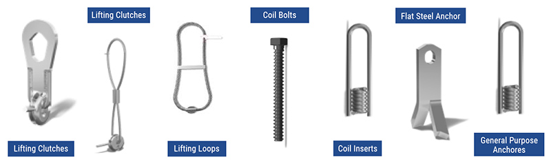
 

Lifting and anchoring system


Before making a selection, we must be the ones who know the component best. Key information includes:

1. Component weight and center of gravity: This is the most crucial data. Not only must the total weight be known, but the location of the center of gravity must also be clearly defined through the design drawings to ensure balanced stress during hoisting and prevent overturning.

2. Concrete strength: The load-bearing capacity of the anchoring system is directly related to the strength of the concrete. The early strength (release strength) and design strength of the component at the time of hoisting must be clearly defined.

3. Component size and shape: Is it a slender beam, a wide slab, or an irregularly shaped component? This determines the possibilities and number of hoisting points.

4. Reinforcement distribution: The anchors must coexist harmoniously with the internal reinforcement mesh of the component to avoid conflict. Detailed reinforcement layout drawings are essential.


Common hoisting and anchoring methods include the following:

(I) Anchoring with Embedded Parts

Embedded parts are one of the commonly used anchoring methods in the hoisting of precast components. The material properties and construction calculations of embedded parts should comply with the provisions of current national standards. During the production of precast components, anchors should be accurately embedded according to design requirements to ensure that their position and quantity meet the hoisting needs. The bearing capacity of embedded parts needs to be strictly calculated to meet the stress requirements under various working conditions during hoisting. For example, when tower cranes, temporary supports, and other equipment are attached to precast components, embedded parts must be set according to stress calculations.

(II) Anchoring with Through-Wall Bolts

For some precast wall components, through-wall bolts can be used for anchoring. During the production of precast components, through-wall holes should be reserved, and relevant reinforcement measures should be designed at this location. The hole diameter and position of the through-wall bolts should be strictly set according to design requirements to ensure the reliability of the anchoring.

(III) Anchoring with Embedded Nuts or Bolts

Embedded nuts or bolts are another commonly used anchoring method. The advantages of this method are convenient lifting and the ability to select the appropriate method based on the corresponding product standards. During the prefabrication of components, embedded nuts or bolts are pre-embedded inside the components, ensuring accurate positioning. During lifting, a special lifting tool connected to the lifting equipment works in conjunction with the embedded nuts or bolts to achieve stable lifting of the components.
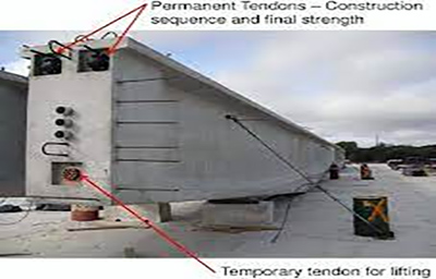
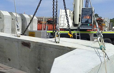
 

Lifting and anchoring systemLifting and anchoring system


Matching component information with anchorage type requires a systematic evaluation of the following five points:

1. Bearing Capacity and Safety Factor

* Absolute Red Line: The rated working load of the anchorage system must be greater than the weight of the component it supports.

* Dynamic Effects: The dynamic factor during lifting (typically 1.5 to 2.5, or even higher) must be considered in calculating the design load.

* Safety Factor: Select certified products with a high safety factor (typically ≥4:1 or 5:1). Never use substandard or counterfeit products.

2. Failure Mode – Concrete is Key

An excellent anchorage system is designed so that the yielding of the steel (lifting rod or anchorage) precedes the failure of the concrete. This means that in the event of overload, you will see a "warning" of steel deformation and elongation, rather than the brittle failure of sudden concrete collapse. Therefore, concrete cone failure calculations must be performed.

3. Number and Layout of Lifting Points

* Basic Principle: Ensure smooth lifting of the component and uniform stress distribution at each lifting point.

* Quantity: Depending on the weight and shape of the component, typically 2, 4, or more lifting points are required.

* Arrangement:The line connecting the lifting points should pass through the component's center of gravity, and the angle between the line and the horizontal plane (sling angle) should generally not be less than 60°. The smaller the angle, the greater the stress on the lifting point.

4. Ease of Installation and Repeatability:

* Disposable vs. Reusable: Embedded anchors are usually disposable, while some specialized lifting tools are reusable, requiring a cost-benefit analysis.

* Installation Speed:In large projects, rapid anchoring significantly improves efficiency.

5. Long-Term Impact on Components:

* Exposed: Embedded internal threaded sleeves can be capped after lifting, having no impact on the building's aesthetics. Exposed anchors may require later cutting, increasing procedures and costs.

* Impact on Structural Performance: Embedded anchors should not weaken critical sections of the component or interfere with prestressing tendons.


Selecting a hoisting and anchoring system for heavy precast components is not a simple matter of "whichever looks best," but a rigorous and systematic engineering decision-making process. It requires us to start with the characteristics of the components, deeply understand the principles of various anchoring methods, and make a comprehensive judgment based on the principles of safety, economy, and efficiency.

Remember, the hoisting and anchoring system is the lifeline connecting the "stationary" and the "moving." Investing extra effort in it is adding the strongest insurance to the smooth progress of the entire project and the safety of everyone involved.

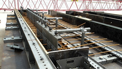
In the precast concrete manufacturing process, the method of fixing the formwork is one of the key factors affecting production efficiency, cost, and product quality. With the development of technology, magnetic systems have gradually become an emerging method of formwork fixing, bringing about many significant changes compared to traditional formwork clamps.


Precast Concrete FormworkPrecast Concrete Formwork


01 Fundamental Differences in Technical Principles

The application of magnetic systems and traditional formwork clamps in precast plants is primarily reflected in their fundamentally different working principles.

Traditional formwork clamps typically rely on mechanical fastening, such as screws, bolts, and clamps, applying physical pressure to the mold to achieve fixation. This method requires pre-drilling or welding into the formwork and platform, with each connection point requiring individual fasteners and manual operation.

Magnetic systems, on the other hand, rely on the strong attractive force of permanent magnets. The magnetic field generated by high-performance neodymium magnets firmly bonds the formwork to the steel platform.

The working principle of magnetic systems is not complex. These devices contain high-performance permanent magnets. A magnetic control box enhances and shields the magnetic force of the internal magnetic blocks, keeping them in an active or inactive state. When the magnetic box is active, the holding surface at the bottom of the magnetic block adheres tightly to the precast concrete production platform, providing a secure hold.

When the magnetic block is pried up with a lever, most of the magnetic force is shielded by the magnetic control box, significantly reducing the bottom magnetic force, allowing the magnetic box to be easily removed from the platform manually. This technology avoids dependence on external energy sources and works entirely based on the physical properties of the magnets themselves.


02 Comparative Analysis of Efficiency and Cost

In precast component production, time is money. The difference in efficiency and cost between magnetic systems and traditional clamps directly determines the project's profitability.

Traditional clamps require drilling, installing screws, and tightening bolts one by one. This process is not only time-consuming but also prone to errors. Taking stair precast component molds as an example, traditional side mold connections require top screw fixing and bottom pin positioning, making the operation complex.

Magnetic systems significantly improve installation speed. Industry data shows that using magnetic systems can reduce template installation time by more than 70%. A simple magnetic box switch can instantly and firmly fix the entire side mold, eliminating the need to adjust each fastener individually.

From a cost perspective, while traditional template clamps have a lower initial investment, their long-term operating costs are higher. Mechanical fasteners are easily damaged and require regular replacement; drilling and welding can cause permanent damage to the mold platform, shortening its lifespan; and labor costs remain consistently high.

In contrast, while magnetic systems have a higher initial investment, they offer significant cost advantages. Once installed, the magnetic device can be reused thousands of times, far exceeding the lifespan of traditional clamps. Since no drilling or welding is required, the formwork and mold table remain intact, significantly reducing maintenance costs.

The precast concrete magnet can withstand a weight of 2100 kg, making it extremely lightweight and suitable for use in precast concrete plants. It can be easily accessed by crane. This strong load-bearing capacity enables it to meet the production needs of the vast majority of precast components.


03 Key Performance Data Comparison

The table below illustrates the performance differences between the magnetic system and traditional template clamps from multiple perspectives:

Comparison Dimensions Magnetic system Traditional template clamps
Installation speed Approximately 30% of the time of traditional methods Baseline time
Disassembly speed Approximately 20% of the time of traditional methods Baseline time
Number of times it can be reused Thousands of times Hundreds of times
Damage to the mold table No damage Drilling and welding are required, causing permanent damage.
Single connection point load-bearing capacity 600-2100 kg Limited by fastener strength
Labor intensity Low cost, requires minimal physical labor The work is demanding, requiring tasks such as tightening screws and drilling.
Adaptability Adapt to multiple templates via adapter Custom fixtures are required.
Temperature adaptability Operating environment up to 80°C Limited by the thermal expansion of materials


The data shows that magnetic systems have significant advantages in terms of efficiency, durability, and adaptability, especially in assembly line production environments where frequent disassembly and assembly of templates are required.


04 Enhanced Quality and Precision

The quality of precast components directly impacts the safety and durability of buildings. In this regard, the magnetic system demonstrates its unique advantages.

Traditional clamps, relying on manual tightening, are prone to inconsistent tightening force, leading to formwork deformation or displacement, which in turn affects the dimensional accuracy of concrete components. This is especially true during vibration table operations, where traditional clamps are prone to loosening and formwork displacement.

The magnetic system, however, provides continuous and uniform clamping force through evenly distributed magnetic points. For example, the LSC-2100 magnetic box has a vertical pull-out force exceeding 2100 kg, and its uniform attraction ensures that the formwork does not shift during production.

The magnetic system also significantly improves the formwork's reset accuracy. Since re-alignment is unnecessary, the formwork can be accurately reset after each assembly and disassembly, greatly improving the dimensional consistency of components during mass production. This is crucial for prefabricated buildings, as the dimensional accuracy of components directly determines the efficiency of on-site installation and the overall quality of the building.


05 Application Scenarios and System Types

Magnetic systems are widely used in precast plants, covering various component production scenarios from simple to complex.

The most basic application is side mold fixing. The side mold is firmly attached to the mold table using magnetic boxes; this is the most common application. Depending on whether the mold table is fixed or vibrating, and the height of the mold (component thickness), different magnetic boxes with varying suction power and sizes can be selected.

For example, when producing composite slabs on a fixed mold table, a magnetic box with a suction power of 600-1000 kg is selected, while a magnetic box with a suction power of 1000 kg is required when producing composite slabs on a vibrating mold table. When producing wall panels, magnetic boxes with a suction power of 1350 kg or 1800 kg are needed.

Magnetic side molds offer a more integrated solution. This type of mold embeds the magnetic suction cup system directly into the steel mold, forming an integrated design. Because the suction cup system is located inside the steel mold groove, concrete residue or other contaminants will not damage the entire mold system.

Embedded component fixing magnetic bases are another important application. When producing precast concrete components, various switch holes and pipe holes need to be left, and various connection or lifting sleeves also need to be pre-embedded. Magnetic bases are used for fixing, which does not damage the platform, ensures the embedded parts do not slip, and guarantees a secure fixation.

In addition, there are specialized tools such as magnetic chamfering strips used to create neat chamfers on the edges of precast concrete components. These rubber magnetic chamfering strips are lighter than iron chamfering strips and also have a certain degree of flexibility, greatly facilitating their use in actual production.


06. Dual Considerations for Safety and Environment

Safety is always paramount in the construction industry. Magnetic systems offer significant improvements in this regard.

Traditional formwork clamps require the use of power tools and welding, posing a high risk of worker injury. Magnetic systems drastically reduce these risks—eliminating the need for drilling and welding, reducing the use of heavy tools, and eliminating sparks and flying metal debris during operation.

Especially in assembly line operations requiring frequent formwork adjustments, traditional methods may require overhead cranes for installation and dismantling, while magnetic systems allow for most tasks to be completed manually, reducing the safety hazards associated with large equipment.

From an environmental perspective, magnetic systems are also more advantageous. Traditional clamps generate significant amounts of metal debris and exhaust fumes during use, while magnetic systems produce virtually no pollutants.

Furthermore, the ability to be reused thousands of times greatly reduces material consumption and waste generation. The reusable nature of magnetic systems makes them a more sustainable construction technology option.


Frequently Asked Questions


Q: How strong is the attraction force of a precast magnetic system?

A: Precast magnetic systems provide reliable attraction force, typically ranging from 500 kg to over 1800 kg per unit, depending on size and design. They are carefully designed to withstand the pressure of new concrete and ensure precise alignment of the formwork.


Q: Is it safe to use a magnetic formwork system near steel molds?

A: Yes! These systems are specifically designed for steel molds. The magnets provide a strong holding force without damaging the mold, and their design ensures a uniform distribution of attraction force, preventing deformation.


Q: Can I add magnets to my existing formwork system?

A: Absolutely. Many magnetic systems are compatible with existing molds. Retrofitting usually requires only minor adjustments and can significantly improve efficiency without replacing major equipment.


Q: What are the maintenance requirements for precast magnets?

A: Magnetic systems have low maintenance costs. Regular cleaning to remove concrete residue and occasional checks for surface wear or corrosion ensure long-term performance and safety.


Q: Are magnetic formwork systems suitable for all types of concrete?

A: Magnetic formwork is suitable for most concrete mixtures, including high-strength concrete, lightweight concrete, and precast concrete. However, for concrete mixtures with very coarse particles or high fiber content, careful placement may be necessary to ensure uniform contact and secure fixation.

Why are Titanium Tubes So Important?

In modern industrial fields, from aerospace to medical devices, from desalination to chemical processing, titanium tubes have become the material of choice in many critical applications due to their superior performance. However, when you need to purchase titanium tubes, you face a fundamental choice: seamless titanium tubes or welded titanium tubes? Understanding the differences and advantages of each is crucial to ensuring project success.

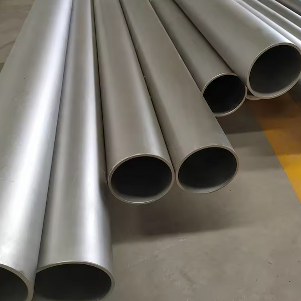
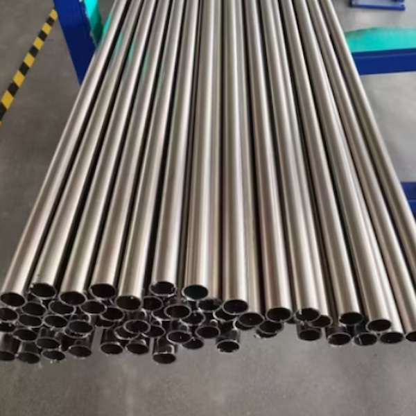
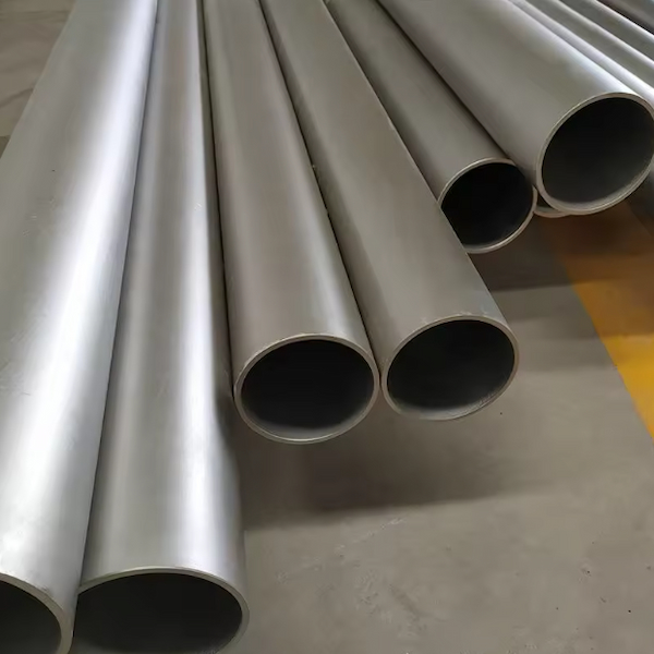
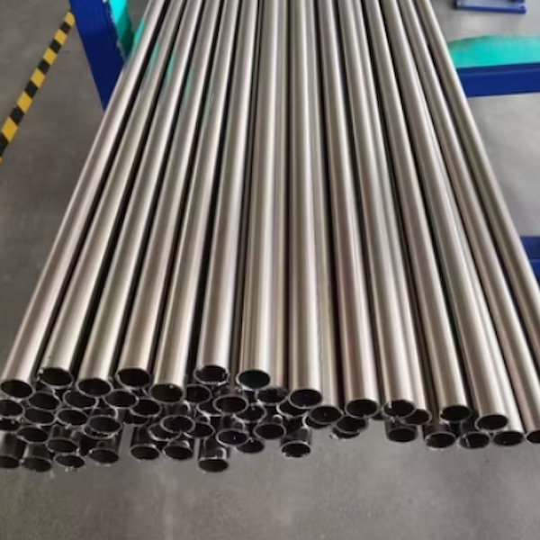
seamless titanium tube

What are Seamless Titanium Tubes?

Seamless titanium tubes are made by heating a solid titanium billet, then perforating it with a piercing machine, and finally processing it through rolling or drawing. The entire process does not involve any welding, so the pipe is structurally completely continuous.

Manufacturing Process of Seamless Titanium Tubes:

Billet Preparation: Selecting high-quality titanium billets

Heating and Perforation: Heating the titanium billet to the appropriate temperature and then perforating it

Rolling and Forming: Forming the tube through a rolling process

Finishing: Achieving the final size and performance through processes such as cold drawing and heat treatment


Unique Advantages of Seamless Titanium Tubes

1. Excellent Structural Integrity

Seamless titanium tubes have no welds, which means the entire pipe cross-section has uniform mechanical properties, without the weak points that welding might introduce. This characteristic makes them more reliable under high pressure, high temperature, or extreme operating conditions.

2. Superior Corrosion Resistance

Because there are no welds, seamless titanium tubes avoid microstructural changes and potential corrosion problems that may occur in welded areas. This is especially important for applications involving corrosive chemicals or seawater.

3. Higher Pressure Resistance

The seamless structure allows titanium tubes to withstand higher internal and external pressures, making them ideal for high-pressure systems (such as aerospace hydraulic systems and high-pressure heat exchangers).

4. Excellent Surface Quality

Seamless titanium tubes typically have smoother inner and outer surfaces, reducing flow resistance and preventing the accumulation of deposits. This makes them particularly suitable for applications requiring high levels of cleanliness, such as medical equipment or food processing.

5. Wide Range of Size Adaptability

Although manufacturing large-diameter seamless titanium tubes is more difficult, for small and medium-diameter pipes, the seamless process provides more precise wall thickness control and dimensional consistency.

Comparison of Seamless Titanium Tubes and Welded Titanium Tubes

Feature Comparison Seamless Titanium Tube Welded Titanium Tube
Welded Titanium Tube Formed in one piece through piercing and rolling Made by rolling and welding titanium plates/strips
Structural Continuity Completely continuous, no welds Has longitudinal or spiral welds
Wall Thickness Uniformity Excellent, precisely controllable Good, but slight variations may occur in the weld area
Pressure Resistance Higher, evenly distributed Good, but the weld may be a weak point under pressure
Corrosion Resistance Uniform throughout, no weld-affected zone Good, but the weld area may have slight differences
Cost Factors Higher, especially for large diameter pipes Relatively lower, especially suitable for large diameter thin-walled pipes
Size Range Significant advantages for small and medium diameters More suitable for large diameter, thin-walled pipes
Production Cycle Relatively longer Usually shorter, especially for standard sizes


Welded titanium tubes are also an excellent choice in many applications:


Cost-effective: For large-diameter or thin-walled pipes, welded titanium tubes are often more cost-effective.

Size flexibility: Extra-large diameter titanium tubes can be produced.

Fast delivery: Standard sizes of welded titanium tubes usually have shorter delivery times.

Technological advancements: Modern welding technologies (such as TIG and plasma welding) can produce high-quality welds.


How to choose: Application scenario guide

Situations for choosing seamless titanium tubes:

High-pressure systems (working pressure exceeding the capacity of welded pipes)

Extreme corrosive environments (especially to avoid the risk of weld corrosion)

High-purity applications (pharmaceuticals, semiconductor industry)

Critical aerospace components

Applications requiring extremely high fatigue life


Situations for choosing welded titanium tubes:

Large-diameter low-pressure pipelines

Cost-sensitive projects with non-extreme operating conditions

Non-pressure-bearing components such as heat exchanger shells

Standard size pipes requiring fast delivery

Large structural components

Standard size titanium pipes

Both seamless and welded titanium tubes have their advantages and applicable scenarios. Seamless titanium tubes are irreplaceable in the most demanding applications due to their superior structural integrity, corrosion resistance, and pressure bearing capacity. Welded titanium tubes, on the other hand, provide a practical solution in cost-sensitive or large-size applications. NBSM provides high-quality seamless titanium tubes and can provide a full range of certification documents.

Titanium—an extraordinary material hailed as the "space metal"—plays a crucial role in aerospace, medical implants, and high-end chemical industries due to its exceptional strength-to-weight ratio, corrosion resistance, and biocompatibility. Seamless titanium tubes are the preferred choice for many demanding applications. But have you ever wondered how these flawless titanium tubes are manufactured? Let's step into the world of seamless titanium tube production.


I. Raw Material Processing

First, all incoming materials undergo inspection. After passing inspection, they are sawn and cut according to process requirements.

II. Forging of Raw Ingots

After heating the ingots, a high-speed forging mill is used to create the blank, followed by electro-hydraulic hammer forging of the raw ingot.

III. Blanking and Turning

The raw ingot is sawn and then machined into a finished bar conforming to process requirements using a lathe.

IV. Piercing

After heating the finished bar, it is pierced using a two-roll or three-roll skew rolling mill to produce a tube blank.

V. Sizing and Straightening

After piercing, the tube blank is sizing and straightened using residual heat to achieve the required dimensions.

VI. Surface Treatment

After piercing, the inner and outer surfaces of the tube blank need to be ground to remove defects.

VII. Cold Working

The tube blank undergoes rolling or drawing processes to produce finished tubes of the required dimensions.

VIII. Heat Treatment

Process standards are strictly followed, and the holding temperature, holding time, and cooling rate are precisely controlled. The temperature uniformity of the heating furnace is regularly tested. The inspector verifies that the heat treatment operation meets the process requirements and issues a heat treatment report.

IX. Straightening 

Straightening is performed using a pipe-specific straightening machine. The curvature must meet the process requirements.

X. Surface Treatment

Polishing or pickling is performed according to the process standards. The inspector checks the surface quality and signs off upon acceptance.

XI. Cutting to Length

The finished pipes are cut to length according to the process requirements using a saw or pipe cutter, and the dimensions are verified.

XII. Warehousing

Before warehousing, the outer diameter, thickness, length, curvature, and other items of the pipes are inspected again. After the inspector confirms that all inspection items are qualified, the pipes are printed with codes, packaged, and put into storage.

Titanium Seamless Tube


Why Choose Seamless Titanium Tubes?

  • Compared to welded titanium tubes, seamless tubes offer significant advantages:
  • Seamless construction, uniform structure, and higher reliability
  • Better pressure resistance and fatigue performance
  • More uniform and isotropic mechanical properties
  • Suitable for more demanding applications
ASTM B338 Titanium Tube

From high-temperature smelting to precision cold working, every step embodies the essence of materials science and engineering. The next time you see fuel lines in aerospace engines, heat exchangers on deep-sea drilling platforms, or orthopedic implants in the human body, you'll know that behind these seamless titanium tubes lies an extraordinary journey from titanium ingots to precision tubing.


In the pursuit of lighter, stronger, and more durable materials, the manufacturing technology of seamless titanium tubes continues to evolve—with more precise dimensional control, superior performance customization, and more environmentally friendly production processes. This is the allure of materials engineering: transforming the elements of the earth into extraordinary products that drive human progress.

If you're planning to create a modern home theater or stylish living room, you might be wondering:


"Can I mount the TV directly on a sound-absorbing wall?"


In short: It's not recommended.


Here are the reasons and the correct installation method.

Top Supplier of Acoustic Wood Slat Panels – Factory Direct

❌ Why you shouldn't mount a TV directly on a sound-absorbing panel


Sound-absorbing panels—especially felt-backed wooden slats—are for absorbing sound, not for bearing weight.


Mounting a TV directly on acoustic panels may result in:


Insufficient structural support


Risk of panel damage


Unsafe installation


Degraded acoustic performance


✔ Correct way to install a TV using acoustic panels


You can perfectly combine a TV wall mount with acoustic panels—simply follow these steps:


1. First, mount the TV bracket on a solid wall.


The TV should be securely fixed to the following wall surfaces:


Concrete wall


Brick wall


Use suitable anchors to secure to drywall


Wooden frame


2. Install the acoustic panels around the bracket.


Leeyin's wood slat acoustic panels are precisely cut to perfectly fit the wall mount, providing a seamless, high-quality look.


3. Hide cables behind the panel.


Our panels have small gaps between the wood slats and felt backing—perfect for concealing cable management.

Want to create a clean, modern, and cable-free TV wall? Acoustic panels—especially wood slat acoustic panels—are a stylish and effective way to hide TV cables while improving room acoustics.


Guangdong Leeyin Acoustics is dedicated to helping homeowners, designers, and builders upgrade their spaces with smart acoustic and aesthetic solutions.

Hot Selling Acoustic Wood Slat Panels

🔧 How to Hide TV Cables Behind Acoustic Panels


✔ 1. Plan the Cable Route


Before installing the acoustic panels, plan the routing of your TV power cord and HDMI cable. The gaps created by the wood slats and felt backing provide a natural cable hiding channel.


✔ 2. Utilize the Gaps in the Wood Slat Acoustic Panels


Liyin's wood slat acoustic panels feature a felt backing and wood slat structure, allowing cables to pass through without altering the panels.


Simply route the cables vertically or horizontally behind the acoustic panels. ✔ 3. Cut a Hole for Cable Socket Installation


You can cut a small hole in the felt backing (instead of the slot) to allow cables to pass through neatly.


Our PET felt is easy to cut, maintaining a seamless look for the panel.


✔ 4. Add Conduit for Heavier Cables


If multiple cables are needed, install thin conduit behind the panel for better cable management and improved airflow.


✔ 5. Mount a TV Bracket Above the Panel


With cables concealed, the TV can be mounted directly on the wall or run through the slot for a clean and aesthetically pleasing look.

A tranquil bedroom is not accidental, but the result of careful design. Whether you're troubled by neighbor noise, street clamor, or indoor echoes, effective soundproofing can significantly improve your sleep environment.


Guangdong Leeyin Acoustics specializes in wood slat wall panels and acoustic panels, providing reliable professional acoustic solutions to customers worldwide.

Hot Selling Acoustic Wood Slat Panels

✔ 1. Install Acoustic Wall Panels


Installing high-quality acoustic panels—such as Liyin's wood slat acoustic panels—helps reduce echoes and absorb unwanted sound reflections.


They can also add warmth and modern aesthetics to your bedroom.


✔ 2. Soundproof Shared or Exterior Walls


For noise penetrating through walls, upgrading to high-density acoustic panels can significantly improve sound insulation.


Liyin's acoustic panels feature high-density felt backing and durable materials for superior sound insulation.


✔ 3. Seal door and window gaps


Even small gaps can leak sound. Use weatherstripping, bottom door seals, or thicker curtains to block noise transmission.


✔ 4. If the noise is coming from upstairs, address the ceiling


For footsteps or impact sounds from upstairs, combine soundproofing panels with additional soundproofing layers or a suspended ceiling soundproofing solution.


✔ 5. Add carpets, soft furnishings, and curtains


Soft materials help reduce noise reflection, creating a more comfortable acoustic environment.

In the realm of critical telecommunications infrastructure, the true test of a structure is not how it performs on the day of installation, but how it withstands decades of relentless environmental assault. For monopole towers exposed to coastal salt spray, industrial pollutants, and harsh climates, corrosion is the primary enemy of longevity. The most effective weapon in this battle is a time-tested, metallurgical process: Hot-Dip Galvanizing (HDG) performed to the stringent ASTM A123 standard. This combination is not merely a coating; it is a comprehensive, long-term defense strategy that forms the cornerstone of a 50-year, minimal-maintenance lifespan.

This blog delves into the science and standards that make hot-dip galvanizing the undisputed choice for ensuring monopole durability.


monopole cell tower


Why Corrosion Protection is Non-Negotiable

A monopole is a singular, load-bearing structure. Unlike a lattice tower where a single corroded member might be replaceable, significant corrosion on a monopole compromises its structural integrity entirely. The cost of replacing an entire tower far exceeds the initial investment in superior corrosion protection. Therefore, the chosen system must be robust, uniform, and self-sustaining for the asset's entire lifecycle. Hot-dip galvanizing meets this challenge through a unique multi-layered defense.


The Hot-Dip Galvanizing Process: A Fusion of Steel and Zinc

The power of HDG lies in the creation of a metallurgical bond between steel and zinc. It is a meticulously controlled, multi-stage process:


  1. · Surface Preparation (The Critical Foundation): The steel is chemically cleaned through degreasing, acid pickling (to remove mill scale and rust), and fluxing. This pristine surface is essential for proper zinc adhesion.

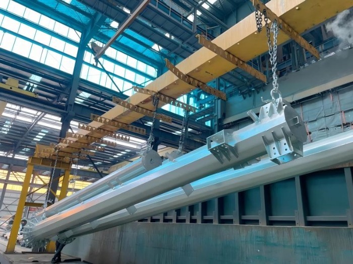
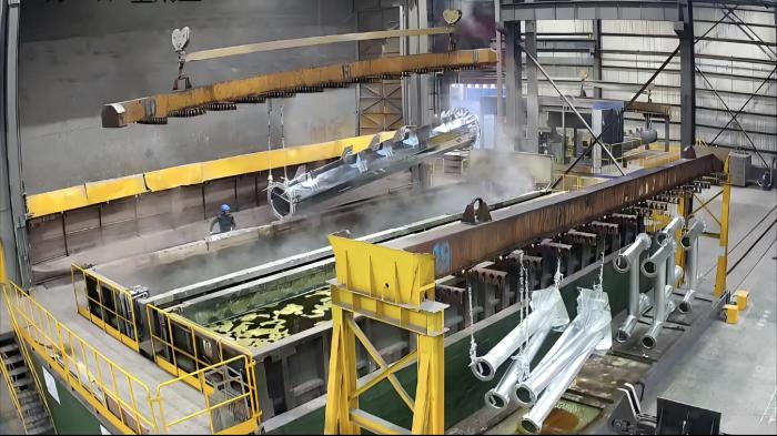
  2. · Galvanizing (The Transformation): The cleaned steel is immersed in a bath of molten zinc at approximately 450°C (840°F). A series of zinc-iron alloy layers form at the steel interface, topped by a layer of pure zinc. This creates a coating that is integrally bonded to the steel substrate—it cannot peel or flake like paint.

  3. · Inspection & Quenching: The newly galvanized piece is cooled, often in a water quench, and inspected for coating uniformity, thickness, and appearance.


hdg monopole tower


The Gold Standard: Understanding ASTM A123

ASTM A123/A123M is the definitive standard for hot-dip galvanizing of iron and steel products. For monopole specifiers, it provides the crucial guarantees of performance:

  1. · Minimum Coating Thickness: The standard specifies minimum average and local coating thicknesses based on the thickness of the underlying steel. For the thick steel plates used in monopoles (often >5mm), this typically translates to a minimum average coating mass of 610 g/m² (approximately 85 µm or 3.4 mils), with higher thicknesses common for severe environments. This substantial zinc reservoir is the "fuel" for decades of protection.

  2. · Adhesion & Uniformity: The process mandated by the standard ensures a consistent, pore-free coating that covers every inch of the steel, including edges and corners—areas notoriously vulnerable with other coating methods.

  3. · Quality Assurance: Compliance with ASTM A123 provides a reliable, repeatable benchmark for quality, giving engineers and asset owners confidence in the long-term performance of their infrastructure.


galvanized monopole cell tower


The Triplex Protection Mechanism: More Than Just a Barrier

HDG provides three distinct, synergistic layers of defense:

  1. · Barrier Protection: The zinc coating forms a dense, impermeable physical shield that isolates the steel from moisture and electrolytes.

  2. · Cathodic (Sacrificial) Protection: Zinc is electrochemically more active than steel. If the coating is scratched or cut, exposing the underlying steel, the surrounding zinc sacrificially corrodes to protect the exposed area. This unique "self-healing" property prevents the undercutting corrosion that plagues painted systems.

  3. · The Zinc Patina: Over time, the zinc surface reacts with the atmosphere to form a stable, adherent layer of zinc salts (the patina). This patina further slows the rate of zinc consumption, contributing to the coating's extraordinary longevity.


monopole communication tower


Engineering the 50-Year Lifespan

Achieving a half-century of service is a function of applying enough zinc to last in a specific environment.

  1. · First-Period Performance: In the initial years, the zinc corrodes very slowly as the protective patina forms.

  2. · Steady-State Corrosion: Once the patina is established, the zinc is consumed at a remarkably linear and predictable rate.

  3. · Predictable Calculation: The expected service life of the galvanized coating can be calculated using the formula: Service Life = (Zinc Coating Thickness) / (Annual Corrosion Rate). In a typical C3 (moderate) atmosphere, an 85 µm coating can last well over 50 years. For severe coastal (C5) environments, specifying an even thicker coating (e.g., 100-120 µm) per the most demanding categories of ASTM A123 directly targets the 50-year goal.


The Economic Imperative: Lifecycle Cost Advantage

While the initial cost of hot-dip galvanizing to ASTM A123 may be higher than basic paint, its Total Cost of Ownership (TCO) is unbeatable.

  1. · Virtually Maintenance-Free: Eliminates the recurring, expensive cycles of inspection, surface preparation, and repainting required for painted structures.

  2. · Prevents Catastrophic Failure: Protects the core structural asset, avoiding the astronomical cost of emergency tower replacement and network downtime.

  3. · Sustainability: The long lifespan and recyclability of both steel and zinc make it an environmentally responsible choice.


Conclusion: An Investment in Permanence

For a monopole, hot-dip galvanizing to ASTM A123 is not an optional finish; it is an integral component of its structural engineering and financial justification. It is a deliberate investment in predictability, resilience, and permanence. By transforming a vulnerable steel tube into a corrosion-resistant sentinel, this process provides the ultimate shield against time, ensuring that our critical communication networks stand tall and functional for generations.


 Learn more at   www.alttower.com


Contact Us

In the competitive landscape of telecommunication and power transmission infrastructure, the upfront engineering design of an angle steel tower is often celebrated for its structural elegance and load-bearing efficiency. However, the true determinant of project profitability and timeline success lies not only in what is designed but in how it is built. A design that looks perfect on paper can harbor prohibitive hidden costs in fabrication, logistics, and field assembly. This is where Design for Manufacturing and Installation (DFMI)—a proactive, holistic engineering philosophy—becomes the critical lever for cutting total project cost and mitigating risk.


angle steel tower


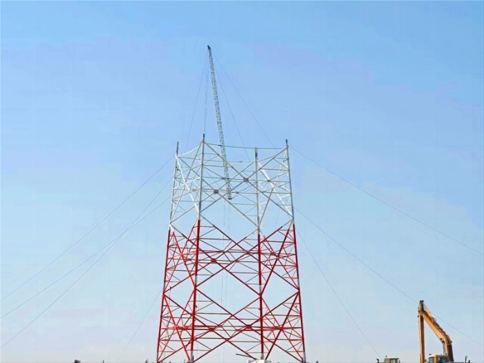
DFMI moves beyond pure structural calculation to integrate the constraints and opportunities of the entaily chain: shop fabrication, transportation, and field erection. Its core principle is simple: optimize the design for the entire lifecycle from workshop to commissioning, thereby eliminating waste, reducing complexity, and accelerating deployment.


The Hidden Cost Killers in Traditional Tower Projects

Before applying DFMI, it's crucial to identify where costs and delays typically hide:

  1. Fabrication Complexity: Excessive unique part numbers, non-standard connection details, and intricate welding requirements drive up shop labor hours, increase material handling, and elevate the risk of error.

  2. Logistical Inefficiency: Components designed without regard to standard trucking dimensions, weight limits, or container sizes lead to costly oversized shipments, complex securing schemes, and multiple trips.

  3. Installation Bottlenecks: Designs that are difficult to sequence, align, or bolt together on-site—especially under challenging weather or in remote locations—result in prolonged crane rentals, higher labor costs, and significant schedule overruns.

DFMI systematically attacks these areas through three pillars: Standardization, Modularization, and Installation-Centric Detailing.


angle steel tower


Pillar 1: Standardization for Fabrication Efficiency

The goal is to reduce variation and simplify the bill of materials (BOM).

  • Standardized Connection Nodes: Instead of customizing each bolted joint, DFMI employs a library of pre-engineered, pre-calculated connection types (e.g., standard gusset plate details for specific force ranges). This allows for:

    1. Batch production of identical components.

    2. Use of jigs and fixtures for faster, more accurate assembly.

    3. Reduced engineering and drafting time for repetitive elements.

  • Minimized Part Proliferation: By rationalizing member lengths and cross-sections, the number of unique part codes can be drastically reduced. This simplifies procurement, inventory management, and quality control in the factory.

  • Design for Automated Processes: Details are tailored for efficient CNC punching/drilling and hot-dip galvanizing. This includes ensuring adequate hole clearances for galvanizing drainage, avoiding trapped air pockets, and designing for easy dipping and handling.


Pillar 2: Modularization for Optimal Transport and Handling

Here, design is governed by the logistics corridor from factory to site.

  1. Transportation Geometry: The maximum dimensions and weight of any shipping module are dictated by standard flatbed trailer or container specifications. DFMI breaks down the tower into the largest possible modules that still comply with these limits, minimizing the number of shipments and crane lifts.

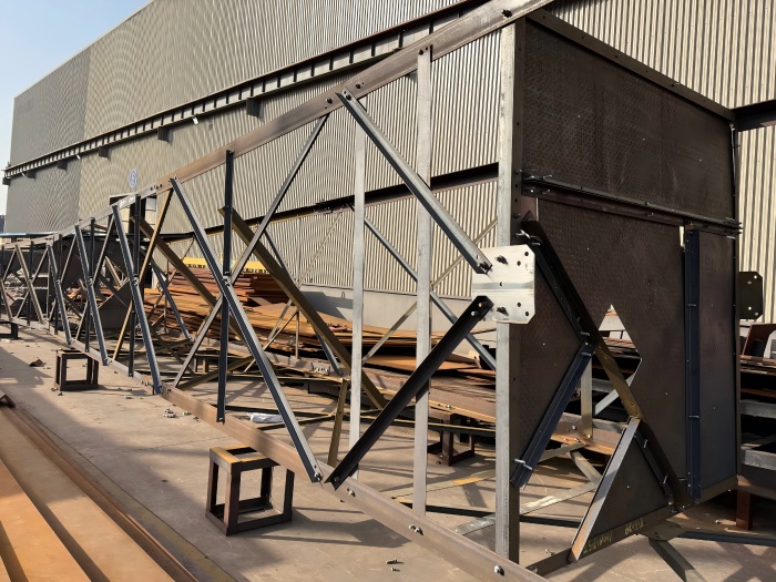
  2. Pre-Assembled Submodules: Where possible, smaller components are permanently joined in the controlled factory environment to form larger, rigid submodules (e.g., complete bracing panels, leg sections with pre-attached ladders). This shifts labor from the challenging field environment to the efficient shop floor, drastically cutting on-site assembly time.

  3. Integrated Lifting and Rigging Points: Lifting lugs or pick points are designed into major modules. Their location is calculated to ensure balanced, stable lifts, and they are fabricated as an integral part of the component, eliminating the need for unsafe and time-consuming field-attached slings.


angle steel tower


Pillar 3: Installation-Optimized Detailing

The design actively enables fast, safe, and error-proof field assembly.

  1. Bolted Connections Over Welding: While not always possible, prioritizing bolted connections for major field splices is a cornerstone of DFMI. This requires precision in hole alignment, achieved through match-marking and the use of drill jigs during fabrication. It eliminates the need for highly skilled field welders, expensive welding equipment, and time-consuming non-destructive testing (NDT) on-site.

  2. Self-Guiding and Self-Supporting Features: Components are detailed to fit together in only one correct way. This can include tapered spigots for leg alignment, unique bolt patterns to prevent incorrect assembly, and temporary connection points for torsional bracing during the erection sequence.

  3. Sequential Erection Clarity: The DFMI process produces clear assembly sequence drawings that guide the erection crew. The design itself facilitates this sequence, ensuring stability at every intermediate stage without requiring excessive temporary supports.


The Tangible ROI of DFMI

Implementing a rigorous DFMI approach yields measurable benefits across the project lifecycle:

  1. Reduced Fabrication Cost: Lower labor hours, less material waste, and higher workshop throughput.

  2. Predictable Logistics: Fewer shipments, lower freight costs, and simplified customs documentation for international projects.

  3. Accelerated Installation: Site work can be reduced by 30-50%, minimizing weather exposure and rental costs for heavy equipment.

  4. Enhanced Quality & Safety: Controlled factory production ensures higher, more consistent quality. Ergonomic and safer installation sequences reduce on-site risks.

  5. Lower Total Cost of Ownership (TCO): While DFMI may require slightly more upfront engineering investment, the savings across fabrication, logistics, and installation overwhelmingly deliver a superior project ROI.


angle steel tower


Conclusion: Engineering for the Real World

For angle steel tower projects, DFMI is not a luxury but a necessity for remaining competitive and profitable. It represents a shift in mindset—from the engineer as a pure analyst to the engineer as an integrator of the entire value chain. By designing with the fabricator's workshop, the truck driver's route, and the erection crew's wrench in mind, we move beyond creating merely adequate structures to delivering optimized assets where efficiency, cost, and reliability are engineered in from the very first sketch. In an industry where margins are tight and schedules tighter, DFMI is the definitive strategy for cutting the hidden costs that traditional design leaves on the table.


 Learn more at   www.alttower.com

Contact Us

In critical emergencies, communication is a lifeline. Traditional emergency communication setups often take days to become operational—a delay that can cost lives. Today, integrated telecom shelters are revolutionizing this process, slashing deployment times to mere minutes. This blog explores how integrated design and advanced technology are redefining rapid response.


integrated telecom shelter


1. The Traditional Emergency Communication Setup: A Race Against Time

Before all-in-one shelters, establishing emergency communications involved:

  1. Transporting multiple vehicles for command, power, and living support.

  2. Manual assembly of generators, antenna masts, and network equipment.

  3. Complex coordination between disparate systems (e.g., satellite, radio, power).

  4. Typical Deployment Time: 24–72 hours, depending on site accessibility and team expertise.


These delays stem from fragmented logistics, incompatible equipment, and labor-intensive processes.


2. The Game Changer: All-in-One Emergency Shelters

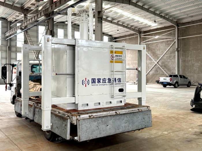
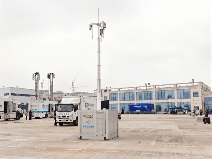
Modern shelters consolidate command, power, and communication into a single, rapidly deployable unit. For example, Sichuan's "shelter fleet" includes a multi-expansion command vehicle that unfolds automatically in 10 minutes and supports up to 70 personnel. Key features enabling this speed include:

2.1 Integrated Systems

  1. Pre-installed Telecom Gear: Satellite, LTE/5G, and radio systems are built in, eliminating on-site assembly.

  2. Unified Power Supply: Onboard generators or batteries eliminate external power setup.

  3. Modular Components: Plug-and-play modules for lighting, computing, and reconnaissance.


integrated telecom shelter


2.2 Rapid Deployment Mechanisms

  1. One-Button Expansion: Hydraulic or automated systems unfold shelters without manual effort.

  2. Lightweight Materials: Advanced alloys and composites reduce weight, accelerating transport and setup.

  3. Standardized Interfaces: Components connect via pre-configured ports, avoiding technical delays.


integrated emergency telecom shelter


2.3 Instant Connectivity


  1. Multi-Network Support: Simultaneous use of satellite, cellular, and ad-hoc networks (e.g., narrowband radio) ensures connectivity even in "blackout" zones.

  2. Self-Organizing Networks: Devices like Hubei's "Feng Su Tong" system autonomously form local networks in 30 seconds.


3. Deployment Timeline: "Days-to-Minutes" in Practice


Phase Traditional Approach All-in-One Shelter
Transport & Setup 12–24 hours (multiple trips) 5–10 minutes (single unit)
Power Activation 2–6 hours (generator setup) Instant (built-in supply)
Network Establishment 4–12 hours (antenna alignment, configuration) 3–5 minutes (auto-connected systems)
Full Operational Readiness 24–72 hours 10–30 minutes


Case in Point: In a simulated earthquake response, Sichuan's shelter fleet established a full command center with communications, lighting, and logistics support in under 30 minutes.


4. Core Technologies Driving Efficiency

4.1 Compact, High-Density Power

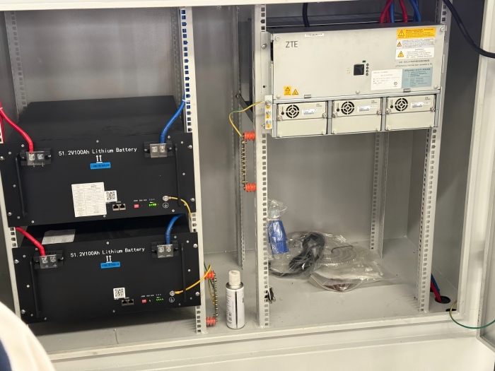
  1. Lithium-Ion Batteries: Support operations without generators, reducing noise and setup steps.

  2. Liquid-Cooled Systems: Solutions like Shenyang Gufen's immersion-cooled shelters ensure stability in high-temperature environments.

4.2 Automated Infrastructure

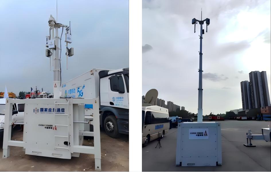
  1. Robotic Antenna Masts: Self-erecting masts with auto-tracking satellites.

  2. AI-Optimized Workflows: Predictive algorithms pre-configure networks based on location and disaster type.

4.3 Modularity and Scalability


  1. Plug-and-Play Peripherals: Add lighting, drones, or sensors without recalibration.

  2. Multi-Mission Flexibility: The same shelter can transition from disaster response to event support in minutes.


emergency telecom shelter


5. Real-World Impact: From Disaster Zones to Event Coverage

  1. Emergency Missions: In Gansu mountain flood rescue, narrowband radio networks restored communications within 3–5 minutes of arrival.

  2. Public Events: During large gatherings, shelters provide temporary coverage without the need for permanent infrastructure.

  3. Military Uses: Mobile launch-control shelters reduce rocket launch setup time from weeks to hours.


integrated telecom shelter


6. The Future: Autonomy and AI Integration

Next-generation shelters will leverage:

  1. AI-Powered Deployment: Systems that autonomously select optimal locations and configurations.

  2. Self-Healing Networks: Algorithms that reroute data automatically around damaged nodes.

  3. Drone Integration: UAVs for aerial reconnaissance and temporary signal relaying.


7. Conclusion: Efficiency as the New Standard

The shift from days to minutes in emergency communication deployment isn't just an improvement—it's a fundamental redefinition of response capabilities. By embracing all-in-one shelters, agencies ensure that when disasters strike, communication—the backbone of coordination and safety—is available almost instantly.


Click here to learn more about the product. 


Contact Us


keyboard_arrow_up